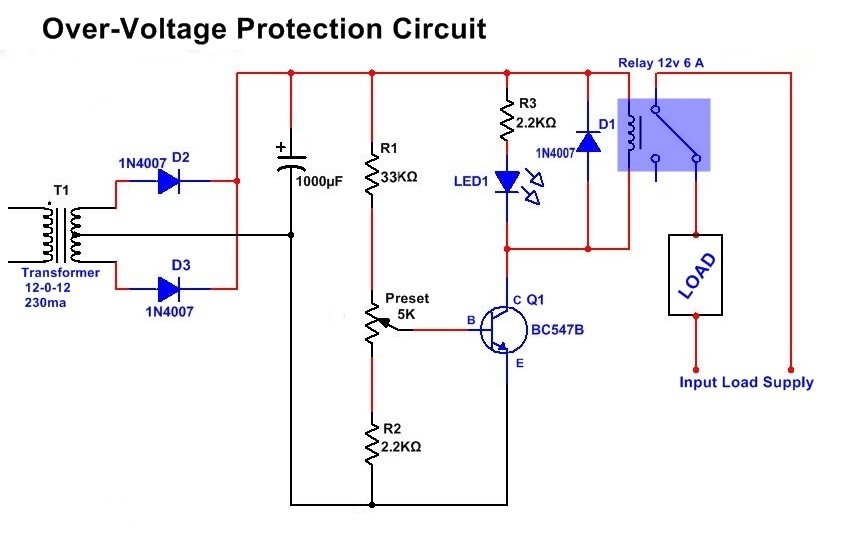
Overvoltage autocut circuit diagram
This Autocut circuit is very easy, simple, and very useful.
Only one transistor and some other components are used in this high-voltage protection Auto circuit.
The load is connected with the NC (normally connected ) Pin of the relay.
This circuit is a very useful auto-cut circuit to protect any electrical or electronic appliance from high voltage. If any device needs 12v to work properly, then this can be damaged by increasing the voltage. This circuit automatically cuts the current supply to any appliance from the input circuit. And when the voltage decreased at a normal level then automatic on the supply is. So it helps to protect the circuit from damage by the high voltage. If you use this circuit for Autocut on over 6v, then use a 6v relay, as the circuit needs 6v.
 Before using this circuit, set the preset and check the relay or output at which the input voltage level relay gets activated. Increase and check the input voltage by multimeter and set the preset at the required position. This circuit can be used for both AC and DC appliances because it uses a relay, but this circuit works only on DC supply power.
Circuit Components & Their Functions:
-
Transformer (T1, 12-0-12V, 230mA):
-
Steps down AC mains voltage to 12V AC.
-
-
Diodes (D2, D3 – 1N4007):
-
Rectify AC voltage to DC.
-
-
Capacitor (1000µF):
-
Smooths the rectified DC voltage.
-
-
Resistors:
- R1 (33KΩ): Sets up voltage division.
- R2 (2.2KΩ): Pull-down resistor for transistor Q1.
- R3 (2.2KΩ): Limits current to LED1.
Preset (5KΩ):
-
-
Adjustable resistor to set the over-voltage threshold.
-
Transistor (Q1 – BC547B, NPN):
-
-
Acts as a switch to control the relay based on voltage input.
-
Diodes (D1 – 1N4007):
-
-
Flyback diode for the relay to prevent back EMF.
-
LED1:
-
-
Indicates when the circuit is triggered.
-
Relay (12V, 6A):
-
-
Disconnects the load when over-voltage occurs.
-
Load:
-
Represents the device being protected.
Circuit Working:
- The transformer (T1) steps down the AC voltage to 12V AC, which is then rectified by D2 & D3 and filtered by the 1000µF capacitor to provide DC voltage.
- The preset (5KΩ) is used to set the voltage threshold at which the circuit will trigger.
- If the input voltage exceeds the preset threshold:
- The base of transistor Q1 gets sufficient voltage.
- The transistor turns ON, activating LED1.
- This also activates the relay, which disconnects the load to protect it from overvoltage.
The D1 diode prevents back EMF from damaging the relay when switching. When the voltage returns to normal, the transistor switches OFF, turning off the relay and reconnecting the load.
Application:
- Protects sensitive electronic devices from high voltage spikes.
- Can be used in power supply circuits for automatic disconnection on over-voltage conditions
At first, when the voltage is under or below the maximum limit ( at which it is adjusted) the maximum voltage drops through the Resistor R2 to the ground, and the Base of the Transistor does not get enough power to switch on the transistor. At this stage, the transistor is in an OFF state, and the Relay does not get supplied and it is not activated.
When the Input voltage of this circuit increases and crosses a level, then the input voltage through resistor R1 and preset also increases and even after dropping the voltage through R3, enough amount of voltage is at the Base of the Transistor Turned On it, and Supply passed Between Emitter and collector. Now Relay is activated, and the supply is disconnected from the appliance. And that is protected from high voltage supply.
Before using it should be adjusted by preset and tested the input voltage and set required the auto cut level according to suitable.
Components
Transformer 12-0-12v 1A -1
BC547 Transistor – 1
1000uf 35v capacitor -1
1N4007 Diode – 1
Resistors
2.2kΩ-2, 33kΩ – 1
Preset – 5K- 1
Difference between 12-0-12 and 0-12 transformer
- Overvoltage Autocutoff circuit using 741 opamp
- Switch ON/Power ON and OFF Delay timer
- AC DC Fan regulator circuit/dimmer
- Dark sensor circuit
- Water level controller circuit
- Touch ON Touch OFF Switch circuit


