The TDA2009 is a high-performance dual-channel audio amplifier IC, commonly used in stereo amplifier circuits. This 10W+10W stereo amplifier provides a simple yet effective solution for boosting weak audio signals to drive 8-ohm speakers efficiently.

Circuit Function and Working
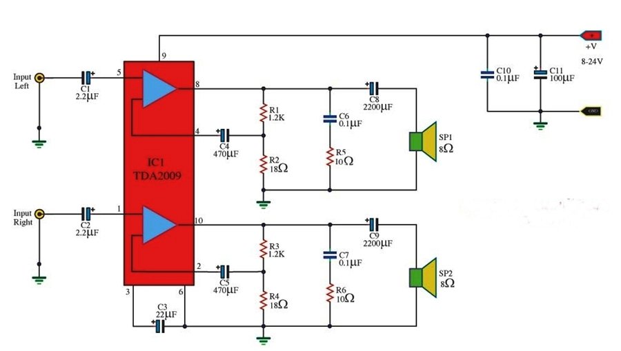
This circuit is a stereo audio amplifier using the TDA2009 IC, designed to amplify both left and right audio channels separately. Here’s how it works:
-
Audio Input Stage:
- The circuit receives stereo audio input from an external source like a mobile, MP3 player, computer, or preamp output.
- C1 (2.2µF) and C2 (2.2µF) are coupling capacitors that block DC components and allow only AC (audio) signals to pass.
- C3 (22µF) provides additional filtering for better sound quality.
-
Amplification Stage:
- The TDA2009 IC amplifies both left and right channels separately.
- Pins 5 & 1 receive the input signals, while pins 8 & 10 are the amplified outputs.
- C4 & C5 (470µF) provide local power supply stabilization for smooth operation.
- Resistors (R1, R2, R3, R4, R5, R6) help control gain and feedback to optimize performance.
-
Speaker Output Stage:
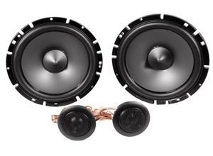
- The amplified signals pass through C6 & C7 (0.1µF) and C8 & C9 (2200µF) before reaching the 8-ohm speakers (SP1 & SP2).
- These capacitors ensure that low-frequency distortions are minimized and prevent DC current from damaging the speakers.
-
Power Supply & Filtering:
- The circuit operates on a single power supply ranging from 8V to 24V DC.
- C10 (0.1µF) & C11 (100µF) are power supply filter capacitors, ensuring stable voltage and reducing noise.
TDA2009 stereo amplifier circuit
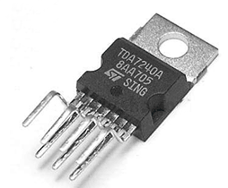
Pin Configuration of TDA2009
| Pin No. | Pin Name | Function |
|---|---|---|
| 1 | Right Input | Right-channel audio signal input |
| 2 | Ground | Common ground connection |
| 3 | Left Input | Left-channel audio signal input |
| 4 | Supply Filter | Power supply noise filtering |
| 5 | Right Output | Amplified right-channel output |
| 6 | VCC (+8V-24V) | Power supply input |
| 7 | Left Output | Amplified left-channel output |
| 8 | Right Feedback | Feedback for right channel |
| 9 | Left Feedback | Feedback for left channel |
TDA2009 IC Specifications
- Type: Dual Audio Power Amplifier
- Output Power: 10W + 10W (at 8Ω, 24V)
- Operating Voltage: 8V – 24V DC
- Low Distortion & Noise
- Short Circuit Protection
- Thermal Shutdown Protection
- Built-in Gain & Feedback for Stable Performance
Applications of TDA2009 Stereo Amplifier
✅ DIY Home Audio Systems – Perfect for small speaker setups at home.
✅ Portable Bluetooth Speakers – Can be integrated into Bluetooth-enabled amplifiers.
✅ Car Audio Systems – Used in stereo car audio applications.
✅ TV & Computer Speakers – Enhances sound quality when connected to PCs or TVs.
✅ Public Address Systems – Can be used in small public announcement applications.
This TDA2009 amplifier circuit is a reliable and efficient solution for stereo audio applications. With minimal external components and high-quality sound output, it is widely used in DIY audio projects.

