DC FAN Speed Regulator Circuit
DC FAN Motor Speed Controller Regulator Circuit Works ON Principle of Pulse Width Modulation (PWM) technique, By Using This Technique Controlling Of DC Motor Speed is very Smoothly And Noise Free.
Introduction Of PWM
Pulse Width Modulation, commonly known as PWM, is a powerful technique used in electronics to control the amount of power delivered to a device. It is widely used in applications such as motor speed control, LED dimming, power regulation, and audio signal processing. PWM allows efficient power control by rapidly switching a signal between ON and OFF states, making it one of the most energy-efficient modulation techniques.
What is Pulse Width Modulation (PWM)?
PWM is a method of varying the width of a pulse (ON time) while keeping the frequency constant. By adjusting the ON time relative to the total period of the signal, the average power delivered to a load can be controlled without significant energy loss.
This technique is particularly useful in systems where analog control is required but only digital signals are available.
How PWM Works?
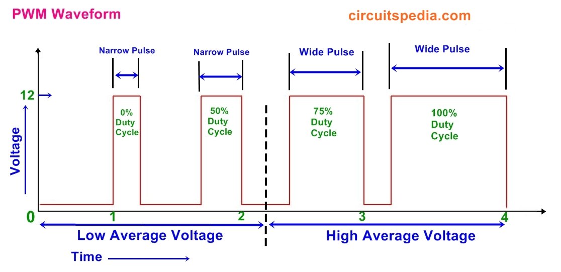
A PWM signal is essentially a square wave that alternates between HIGH (ON) and LOW (OFF) states. The key parameter that defines PWM behavior is the duty cycle:
- Duty Cycle (%) = (ON Time / Total Time) × 100
- A higher duty cycle means more power is delivered (brighter LED, faster motor speed, higher voltage output).
- A lower duty cycle reduces power (dim LED, slower motor speed, lower voltage output).
Examples of PWM Duty Cycle:
- 100% Duty Cycle: Continuously ON, delivering maximum power.
- 50% Duty Cycle: ON for half the time, OFF for the remaining half.
- 25% Duty Cycle: ON for 25% of the time, OFF for 75%, reducing power output.
By adjusting the duty cycle, PWM effectively controls voltage and current without generating excess heat or wasting energy.
Common Uses of PWM
PWM is used in various applications, including:
1. Motor Speed Control
PWM is widely used in DC motor controllers to regulate speed efficiently. Instead of using resistors to limit voltage (which wastes energy), PWM delivers only the required power, reducing losses and improving performance.
2. LED Brightness Control
Dimming LEDs with PWM prevents energy loss by controlling brightness through duty cycle variation instead of reducing voltage.
3. Audio Signal Processing
PWM is used in Class D audio amplifiers, converting analog signals into high-frequency digital pulses for efficient amplification.
4. Power Regulation
Switching regulators and power inverters use PWM to maintain a stable voltage output by adjusting duty cycles dynamically.
5. Communication Systems
PWM is used in signal modulation techniques where information is encoded within the pulse duration.
- A PWM signal is a square wave that switches between ON (High) and OFF (Low) states.
- The duty cycle represents the percentage of time the signal stays ON in one complete cycle.
- A higher duty cycle means more power is delivered, while a lower duty cycle means less power.
Example of PWM Duty Cycle
- 100% duty cycle → Fully ON (continuous signal)
- 50% duty cycle → ON for half the time, OFF for the other half
- 25% duty cycle → ON for 25% of the time, OFF for 75%
Applications of PWM
- Motor Speed Control – Used in DC motors to vary speed efficiently.
- LED Dimming – Adjust brightness by changing duty cycle.
- Audio Signal Processing – Used in class D amplifiers.
- Voltage Regulation – Switching regulators use PWM to maintain constant output.
• The term duty cycle describes the proportion of ‘on’ time to the regular interval or ‘period’ of time; a low duty cycle corresponds to low power, because the power is off for most of the time. Duty cycle is expressed in percent, 100% being fully on.
The PWM method is a great method to control the amount of power delivered to a load without initiating the waste power.
• Average Output Voltage is Proportional to ON Time Of Duty Cycle.
PWM signals are used for a wide variety of control applications. Their main use is for controlling DC motors but it can also be used to control valves, pumps, hydraulics, and other mechanical parts. The frequency that the PWM signal needs to be set at will be dependent on the application and the response time of the system that is being powered. Below are a few applications and some typical minimum PWM frequencies required:
- Heating elements or systems with slow response times: 10-100 Hz or higher
- DC electric motors: 5-10 kHz or higher
- Power supplies or audio amplifiers: 20-200 kHz or higher
The following are the advantages and disadvantages of controlling the speed of a DC motor with PWM are
Advantages
- High Efficiency – Minimizes power loss by switching between ON and OFF states instead of dissipating excess energy as heat. The efficiency is up to 90%
- Precise Control – Allows fine-tuning of speed, brightness, or power delivery.
- Energy Saving – Ideal for battery-powered devices due to low energy consumption.
- Versatile – Used in a wide range of applications, from motor control to data transmission.
- Due to heat, there is a less amount of energy is decreased
- It will allow the fine motor control
Disadvantages Must Read What is 555 Tmer
- Circuit Complexity – Requires additional components like transistors, MOSFETs, or microcontrollers to generate PWM signals.
- Electromagnetic Interference (EMI) – High-frequency switching can introduce noise in nearby circuits.
- Radio frequency interface
- Voltage Spikes – Rapid transitions between ON and OFF states may create unwanted voltage spikes.
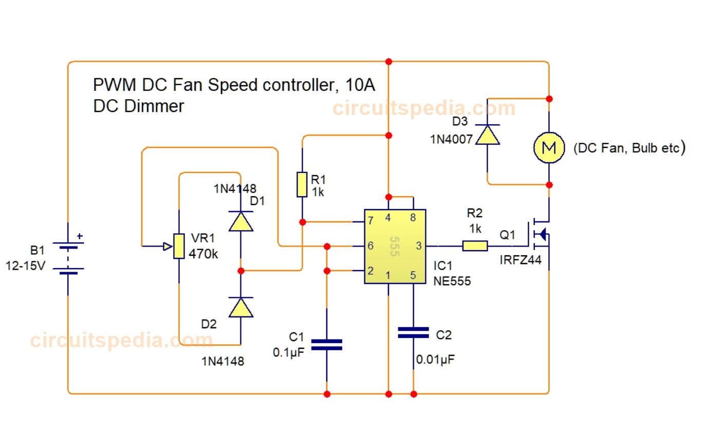
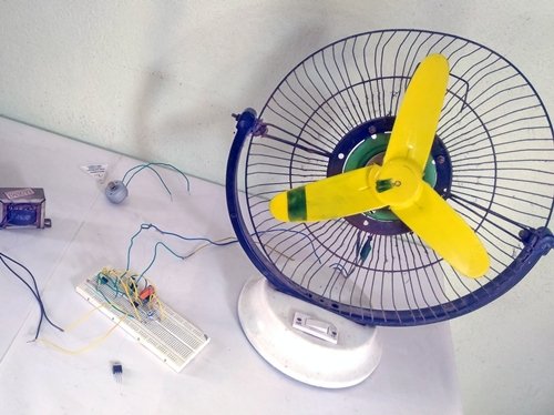
Here is a circuit diagram of DC fan Regulator Using the PWM Method.
By This Method Smoothly Controlled The Speed Of DC Motor At Negligible Noise
BY using This Circuit, You can control the speed of the DC Fan by tuning the (Potentiometer) volume control variable resistance. These circuits are based on the 555 Timer.
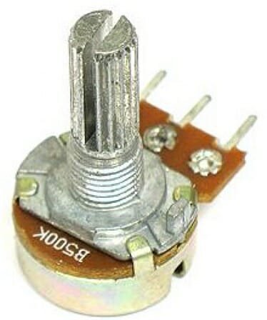
Use at least 470K POT ( Vol control potentiometer) to set the required speed
Don’t Forget To Read Remote Controlled ON OFF Switch circuit With Video
circuit diagram of DC Fan Speed controller.(Tested on 12v Motor)
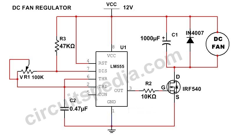
Circuit 2.
DC motor controller using 555 timer and MOSFET IRFZ540
Circuit 3.
DC Dimmer circuit 10A using PWM
(100% working-Tested)
FAQs on PWM (Pulse Width Modulation)
1. What is PWM in electronics?
PWM (Pulse Width Modulation) is a technique used to control power delivery by varying the duty cycle of a square wave signal. It is commonly used in motor control, LED dimming, and power regulation.
2. How does PWM work?
PWM works by switching a signal between ON and OFF states at a high frequency. The proportion of time the signal stays ON (duty cycle) determines the amount of power delivered to the load.
3. What is the duty cycle in PWM?
The duty cycle is the percentage of one cycle in which the signal remains in the ON state. It is given by:
Duty Cycle=(Time ON/Total Period)×100%
For example:
- 100% Duty Cycle → Fully ON
- 50% Duty Cycle → Half ON, Half OFF
- 0% Duty Cycle → Fully OFF
4. What are the advantages of PWM?
- Efficient power control (reduces energy loss in electronic circuits).
- Precise control of motor speed, LED brightness, and voltage levels.
- Low heat generation compared to analog control methods.
- Works well with digital circuits and microcontrollers.
5. What are the common applications of PWM?
- Motor speed control (DC motors, servo motors, and stepper motors).
- LED dimming (used in displays and lighting systems).
- Power supply regulation (switching power supplies and inverters).
- Audio signal processing (class D amplifiers).
6. What are the types of PWM?
- Fixed Frequency PWM – The switching frequency remains constant while the duty cycle changes.
- Variable Frequency PWM – Both frequency and duty cycle change as needed.
- Phase-Correct PWM – Used in applications requiring symmetrical waveform generation.
7. What is the difference between PWM and analog control?
PWM uses digital switching to control power delivery, while analog control uses continuous voltage variations. PWM is more efficient because it reduces power loss and heat dissipation.
8. Can PWM be generated using microcontrollers?
Yes, most microcontrollers (like Arduino, PIC, STM32, etc.) have built-in PWM modules that generate PWM signals using timers.
9. What is the effect of PWM frequency?
- High frequency reduces flickering in LEDs and ensures smooth motor operation but may cause switching losses.
- Low frequency is useful in some applications but can lead to noticeable fluctuations.
10. How does PWM control motor speed?
PWM controls the average voltage supplied to a motor by switching the power ON and OFF rapidly. A higher duty cycle increases speed, while a lower duty cycle decreases speed.
11. What is the relation between PWM and voltage?
The average output voltage of a PWM signal is proportional to the duty cycle. For example, if the supply voltage is 12V and the duty cycle is 50%, the average voltage is:
Vout=12V×0.5=6V
Also Read– How to Make LED Indicator For 220v AC
Also Read – 12V DC To 220V AC Homemade Inverter Circuit

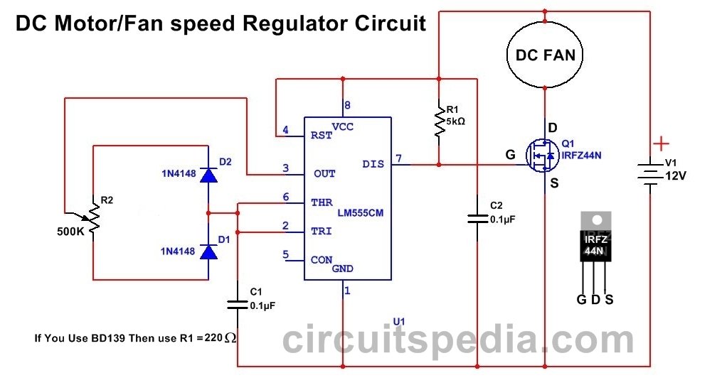

I built circuit 1, but the motor runs at full speed regardless of VR1 setting. I can’t find any errors in my wiring, so I’m puzzled as to what is going on. Can you suggest what I should check? I have an oscilloscope that I can use as well as the usual multimeter.
Many thanks in advance
There was an error with connection of D2, Actually polarity was wrong in diagram by mistake.
Now it is corrected
use this circuit
The diode D2 in circuit 1 is the wrong way around! The cathode should be connected to pin 7 of the 555. As the circuit is drawn now the motor wil run at full speed with no control.
You are right
Now Corrected