Simple clap switch circuit diagram 220v using relay
High-Sensitive Clap operated switch circuit Without Microcontroller. When clapped, the Connected Load is Switch ON. Again Clap, the Load is switched OFF. A condenser mic works as a sound sensor.
You can Switch ON and Switch OFF the Appliance At your Room by simply clapping or by a Sound.
Introduction
A clap or sound-operated switch circuit is a simple yet powerful electronic system that allows users to control electrical appliances (such as lights, fans, or other devices) by simply clapping or making a sound. This circuit is useful for automation, particularly for individuals with mobility challenges or for smart home applications.
This article will explain the circuit connections, working principle, functions, and the ICs used in this design based on the provided circuit diagram.
Construction
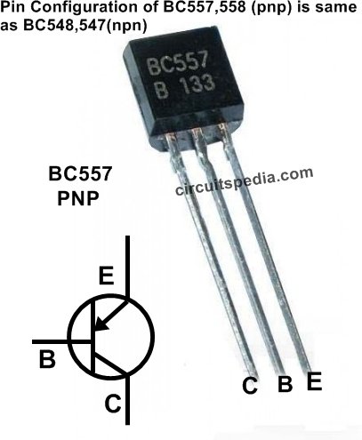
Connect All the required components as given in the diagram. Enclose the condenser microphone to As possible as much possible sound Reach easily to this. Use all the Resistors as given value for more sensitivity and set the preset by moving. You can use the 2N2222 Transistor as place of 548. 2N2222 has fast switching. Keep in mind that Condenser MIC has polarity, so if the circuit is not working, then check the polarity of MIC. The Pin Configuration of BC548 and BC558 is the same, but the 2N2222 transistor pin configuration is different.

1. Power Supply
- V1 (6V Battery/Power Supply): Provides the required power for the circuit.
- The circuit operates at 6V DC, which powers all components, including the LM358 Op-Amp, transistors, and 4017 IC.
2. Sound Detection Section
- Microphone (MIC): A condenser microphone is used to capture sound waves (like a clap) and convert them into electrical signals.
- VR (5K Potentiometer): This is used to adjust the sensitivity of the microphone.
- R6 (10KΩ Resistor): It acts as a pull-down resistor for proper operation of the MIC.
- The signal from the MIC is fed into an operational amplifier (LM358) for amplification.
3. Amplification & Signal Processing
- IC1 (LM358 Op-Amp): It is a dual operational amplifier used to amplify weak electrical signals from the microphone.
- R1 (1KΩ Resistor): Sets the gain for amplification.
- C1 (2.2µF Capacitor): Used for coupling and filtering unwanted noise.
- Q1 (BC548B NPN Transistor): Acts as a switch to process the amplified signal.
- Q2 (BC558B PNP Transistor): Helps in inverting and conditioning the signal before passing it to the 4017 Decade Counter IC.
4. Decade Counter & Switching Section
- IC2 (4017 Decade Counter IC): This IC is the core component for toggling the output state ON or OFF upon receiving a valid sound signal.
- R2 (3.3KΩ) & R3 (30KΩ) Resistors: Used to bias the transistors properly.
- LED1 (Indicator LED): Turns on to indicate circuit operation.
- R5 (1KΩ Resistor): Limits current to the LED to prevent damage.
- D1 (1N4007 Diode): Protects the circuit from back-emf generated by the relay coil.
5. Relay & Load Control Section
- Q3 (BC548B NPN Transistor): Works as a relay driver.
- R4 (470Ω Resistor): Controls base current to Q3.
- Relay (6V): Controls the AC appliance (e.g., 220V lamp, fan, or other electrical loads).
- X1 (Load – AC Appliance): The device being controlled, which could be a lamp or fan.
Clap switch circuit working principle
1. Sound Detection
- When a sound (e.g., a clap) is detected by the microphone, it generates a small electrical signal.
- This signal is amplified by the LM358 op-amp to a usable level.
2. Signal Processing and Triggering
- The amplified signal is processed by Q1 and Q2 transistors, ensuring it is strong enough to trigger the 4017 Decade Counter IC.
- The 4017 IC toggles between ON and OFF states each time it receives a valid pulse.
3. Switching the Appliance
- The output from 4017 IC is used to switch Q3 transistor, which in turn activates the relay.
- When the relay is activated, it connects the AC supply to the load (e.g., a lamp or fan), turning it ON.
- A subsequent sound pulse (clap) toggles the state, turning the appliance OFF.
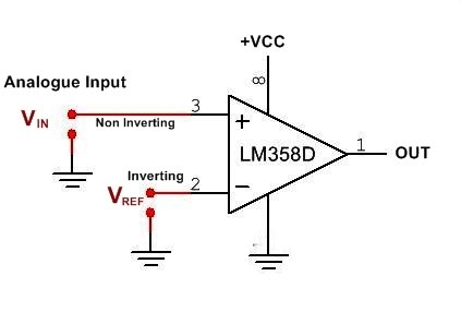
At first, when the Circuit is switched ON but not clapped, the condenser mic no detect any sound, and at this condition, the resistance through this is very high, and the voltage level at pin 2 (Vref) is very Less in comparison with Pin 3 (Vin). In this case, the output is 0.
When clap, the sound is detected by the condenser mic and the resistance between vcc and pin 2 is very less, and the voltage level get increases in comparison with the voltage level between vcc and pin 3. In this case, the Output is changed, and it is now Turn Low to High.
The signal input at pin 14 of 4017 changes as the output at pin 2 changes from Low to High. Again, when the input at pin 14 is changed, the output at pin 2 changes from High to Low.
According to the output of pin 2, transistor Q3 is turned ON and OFF, and the relay is activated; therefore, the appliance is ON OFF by clap.
ICs Used in the Circuit
1. LM358 Operational Amplifier
- Function: Amplifies weak signals from the microphone.
- Why Used?: It provides high gain with low power consumption, making it ideal for sound detection applications.
When the voltage at Vin is more than Vref then the output is 0v (-vcc)
When the voltage at Vin is Lower then Vref then output is High (+vcc)
2. 4017 Decade Counter IC
- Function: Acts as a toggle switch, changing states upon receiving a pulse.
- Why Used?: It simplifies circuit design, eliminating the need for complex logic circuits.
Applications
- Home Automation: Allows users to turn ON/OFF appliances using sound signals.
- Smart Lighting: Hands-free control of lights, useful in modern homes and smart environments.
- Assistive Technology: Helps individuals with disabilities control electronic appliances.
- Security Systems: Can be integrated into alarm systems where a sound-triggered switch is needed.
- Interactive Projects: Used in robotics and IoT applications where sound-activated switches are required.
Advantages
- Hands-Free Operation: Ideal for users who cannot manually switch devices.
- Low Power Consumption: Uses minimal power, making it energy-efficient.
- Simple & Cost-Effective: Easy to build using common electronic components.
- Reliable Performance: Works efficiently in detecting claps or sound signals.
Conclusion
The clap/sound-operated switch circuit is a simple yet highly effective system for controlling electrical appliances using sound signals. With the help of LM358 (Op-Amp), 4017 Decade Counter IC, transistors, and a relay, this circuit provides a cost-effective solution for home automation and smart switching applications.
By understanding its components, working principle, and applications, users can integrate this technology into various DIY projects or commercial systems. Whether for home automation, security, or assistive technology, this circuit is a great step towards a smart and efficient control system
Also Read Stereo Audio Amplifier circuit
This circuit is tested on 6v supply
components
IC
4017-1
358-1
Transistor
BC548 or 547-2
BC557 or 558-1
Capacitor
2.2uf 25v-1
Resistor
3.3K-1
1K-1
10K-1
30K-1
470Ω-1
Preset-Tested with 5K (10K would be better)
Other
Condenser MIC-1
LED-1
Relay 6v -1
Diode-1N4007-1
Also Read Touch Switch for ON OFF Light/Fan
Must Read DC FAN speed Regulator using PWM


Rattling excellent information can be found on website . “Life without a friend is death without a witness.” by Eugene Benge.
Hello there,
My name is Aly and I would like to know if you would have any interest to have your website here at circuitspedia.com promoted as a resource on our blog alychidesign.com ?
We are in the midst of updating our broken link resources to include current and up to date resources for our readers. Our resource links are manually approved allowing us to mark a link as a do-follow link as well
.
If you may be interested please in being included as a resource on our blog, please let me know.
Thanks,
Aly