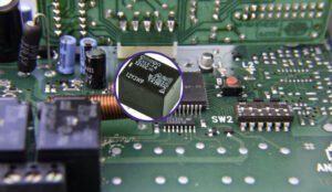
How does a relay work
RELAY
Due to the occurrence of an open-circuit fault or short short-circuit fault electrical equipment is getting damaged. In order to avoid that we need to sense the electrical quantities such as voltage, current continuously by using a sensing device is known as a relay.
Relay Working principle
A relay consists of a mechanism to make or break connections in an electric circuit. This mechanism can be electromagnetic, thermal, or electronic type.
Thus relay can be operated by one circuit to switch to another circuit. Thus, it provides complete electrical isolation between the controlling circuit and the controlled circuits.
When a short circuit fault takes place, current through the relay will be more than its rated value or set value then the operating force is greater than the restraining force; then the relay will operate, initiating the action of the circuit breaker to isolate the fault.
Relay construction
Relay consists of three basic elements
- An actuating element called initiating coil
- Linkage to transfer the actuation/ de-actuating of input to output.
- Output elements or contacts.
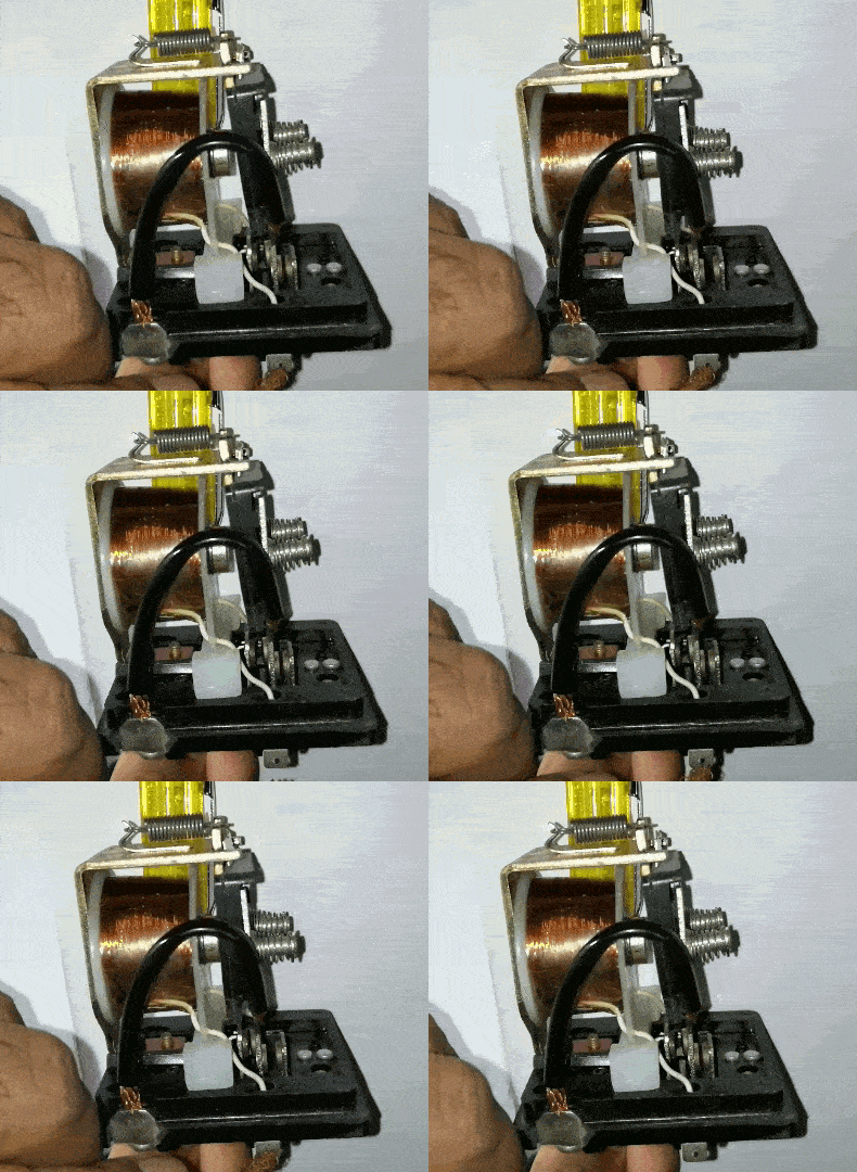
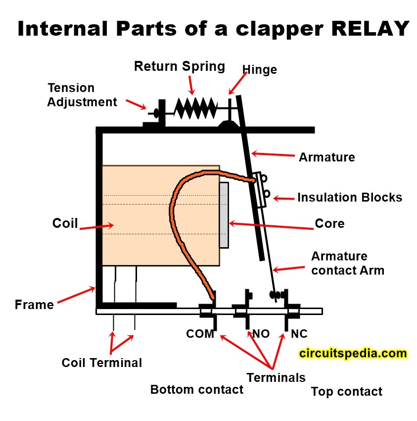
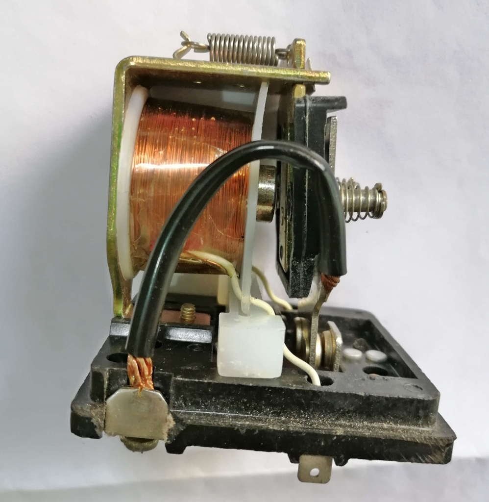
Fig shows the construction of a general-purpose electromagnetic relay. It contains a core surrounded. By coil of wire, the core is mounted on a metal frame. The movable part of the relay is called the armature. When a voltage is applied to the coil, the current flowing through it produces a magnetic field in the core. In other words, the core acts as an electromagnet and attracts the metal armature. When the armature is attracted to the core, the magnetic path is from the core through the armature, through the frame, and back to the core. On removing the voltage, the spring attached to the armature returns the armature to its original position. In this position, there is a small air gap. Hence, more power is needed to pull in the armature than that needed to keep it in the attracted position.
The relay contacts and terminals are mounted on an insulated board. When no current flows through the relay coil, the contact arm touches the top contact when coil is attached on the flow of current, the armature along with the contact arm assembly, moves downwards so that the contact arm touches the bottom contact.
Classification of relays
Relays can be classified in many ways depending upon their function, input, output, applications, and performance characteristics.
1 .Relay classification by function:- According to function relays are categorized as-
- Monostable relay:– A relay whose contacts return to the original position after the excitation is switched off. they are further neutral, polarised, and AC voltage types.
- Bistable relay: – Relay whose contacts remain in the charged position after the excitation in removed. The contacts change over to another position by an emerging current of the opposite direction. There are further polarized and remnant types.
2. Relays classified by outputs:– Relays are classified as follows according to output.
- Low voltage DC load
- Medium voltage wattage DC load
- High wattage DC load
- Low wattage AC load
- Medium wattage AC load
- High wattage AC load
- Specialized relay
3 .Relays classified by input: – According to input relays are classified as:
- Direct current
- Alternating current
4 .Relay classified according to an application: – The relays are classified as follows on the basis of application:
- Commercial
- Industrial
- Military
- Communications
- Railways
5 .Relay classified by performance: – Relays are classified by what they can do and are required to do, there are
- General-purpose
- Special purpose
- Definite purpose
Relay performance
Relay being an electromechanical device does not respond instantaneously. Relay performance presents a series of events on both energization and de-energization. The terms related to relay performance are –
- Operation time: – This is the interval between the closing of the emerging circuit and the instant of first opening or closing of a break contact.
- Release time: – this is the time interval between the emerging circuits of the monostable relay after switch off and the instant of the first opening of a make contact or first closing of a break contact.
- Bounce time: – The interval of time between the first and final closing or opening of the relay contact.
- Reverse operate time: – This is the time interval between the closing of the emerging circuit and the instant of the first opening of a make constant or first closing of a break contact.
- Duty cycle: – It is the ratio of pulse width (on time) to the cycle time with repetitive energization
- Cycle time:- Sum of the duration of on-time and the time interval of the periodically energized relay
Definitions and specifications
A clear understanding of the following terms helps to understand of specifications of various types of relays.
Terms related to relay function
- Neutral position:- For a monostable relay, the position in the de-energized state for a bistable relay, the position declared by the manufacturer.
- Functional position:- for a monostable relay it is the energized state and for the bistable relay, it is the position inverse to the off position.
- Bounce: – One or more temporary openings or closings of the relay contacts during the switching operation.
- Terms related to relay energizing: –
- Excitation: – Electrical circulation of the magnetic circuit by means of an energizing current through the winding of the relay.
- Nominal value (voltage, Current, Resistance etc):- It is the value to meet the specification for which the relay has been designed.
Common Types of Relays
Electromagnetic relays are manufactured in a wide variety of sizes shapes and types to meet different requirements. The basic principle of operation remains the same as discussed earlier.
The commonly used relays are
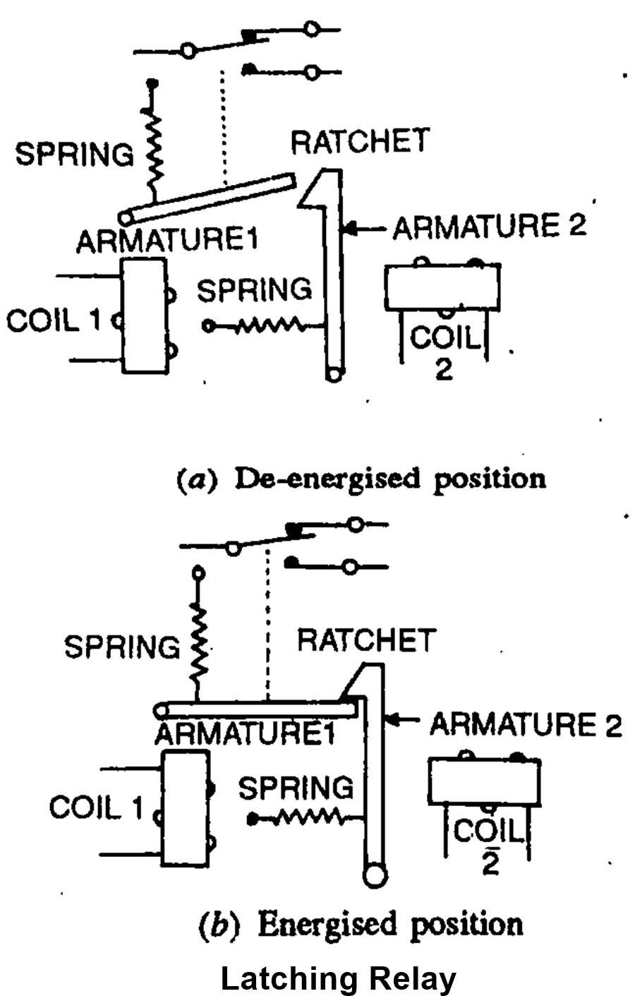
- Latching Relays – these are used in overload and alarm circuits. Relay is energized or de-energized, it states in that position as shown in fig.
These are like clapper relays as discussed earlier but they do not need continuous current through the coil to keep them in open or closed position. A short pulse of sufficient amplitude is enough to close the relay.
It has two coils end a mechanical ratchet for latching. A small current pulse to coil causes the armature to pull in and stay latched. A short pulse when applied to coil 2 causes the armature to go for the normal position.
- Ratchet Relay – this is again a clapper type relay which does not need continuous current through its coil to remain in operation. It operates like a latching type relay. Instead of holding down an armature as in a latching relay. Each current pulse through relay coil causes a sprocket and can assembly to move one position. The insulated cams on either end of camshaft are made from Bakelite and hold the contacts opens or closed.
- Rotary stepping relay – it is a combination of a ratchet relay and rotary switched and is used to connect one or more input circuits to an output circuit chosen from a sizable group of circuits. Its response to current pulses Rippled internally. Rotary stepping relays consist of three parts.
- Driving mechanism
- Basic assembling
- Wiper assembly
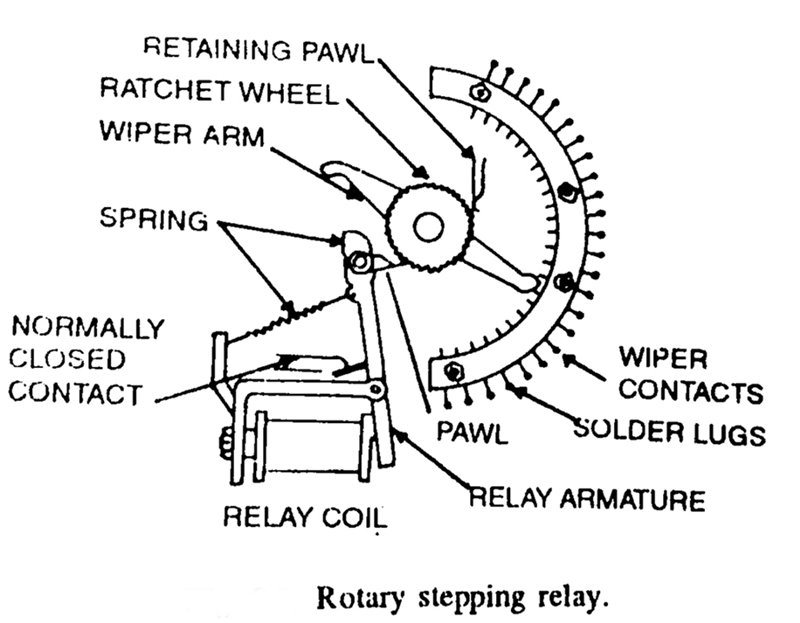
These stepping switches are stepped by a pawl and ratchet mechanism as shown in fig. making one step for each current pulse applied to switched coil pawl is connected to the relay armature. It causes the wiper arm to step from one contact to another. When a voltage is applied to the relay coil. The wiper can be positioned to any one of the twenty-four wiper contacts.
The relay has two wiper arm mounted on the same shaft. These are located opposite each other. So that when one of the arms has passed over the entire set of contacts. The second wiper arm begins passing over the contacts. A ratchet wheel is also mounted on the shaft. There are twice as many teeth on a ratchet as there are contacts.
The relay rod and armature are used together with pawls to move the ratchet wheel.
When a voltage is applied to the relay coil, the armature gets attracted to the armature core. This causes pawl at the opposite end to rotate the ratchet and step the wiper arms one position. The retaining pawl prevents the ratchet wheel from moving backward when the relay coil is de-energized. The spring returns the armature to the original position.
The stepping switch usually has more than one bank of contacts with a pair of wiper arms. Some rotary stepping switches have up to sixteen banks. These are used extensively in machine tool control, conveyor systems, test equipment and communication switching.
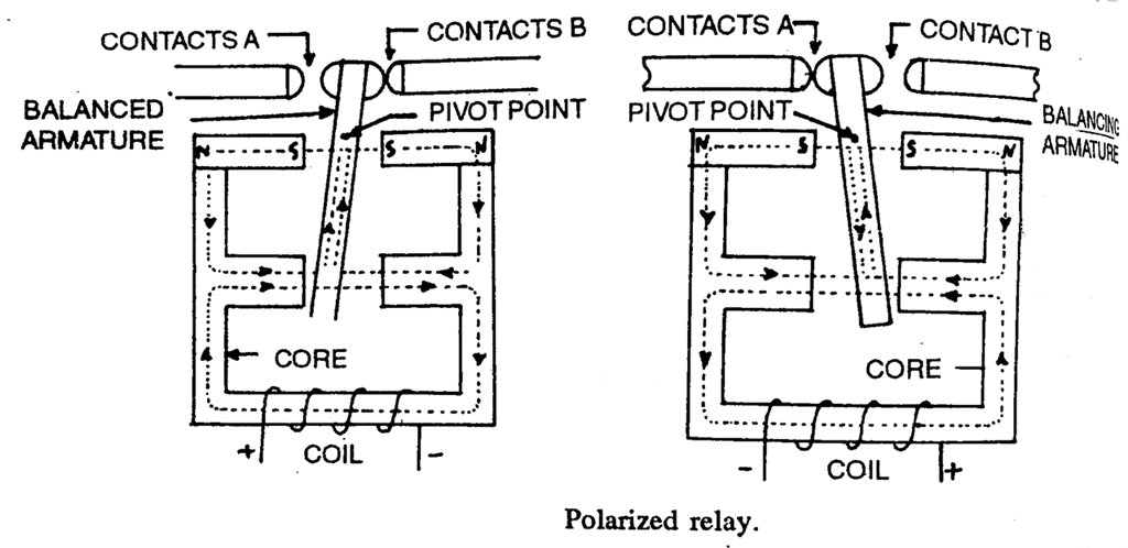
- Polarized Relay – In an ordinary relay, its operation is not affected by the direction of flow of current. The armature moves irrespective of the direction of the current in coils. However, polarized relays are sensitive to the polarity of an applied voltage. The contact closure they provide varies with the polarity of the applied voltage.
They have magnetic flux in addition to the flux provided by the relay coil. This fixed flux is provided by the permanent magnet. It provides sufficient initial pull and hence small addition pull is required. This small pull can be derived from magnetic flux generated by a small current in the coil. This relay requires less power. It is very sensitive and very fast operating.
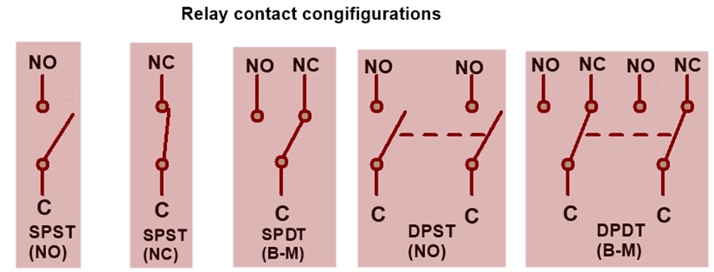
Depends on the poles and throws, relays are classified into
-
Single pole single throw (DPST)
-
Single pole double throw (SPDT)
-
Double pole single throw (DPST)
-
Double pole double throw (DPDT)
Poles and Throws
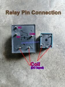
Every relay has an input contact terminal and an output contact terminal. The input terminal is called as pole and the output terminal of the relay is called the throw. The output terminal contact is fixed and generally, there is no moving parts attached to this. The input terminal pin is also referred to as the common (C) pin contact. A movable pin can be attached to the Common or input terminals.
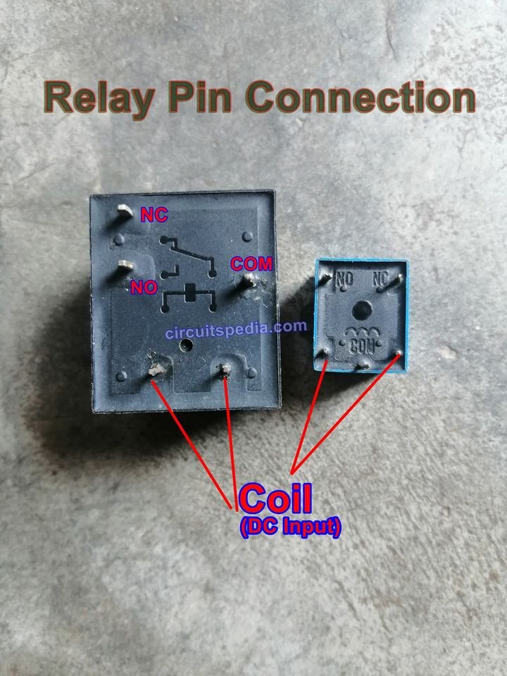
NC (Normally Closed) – Normally closed is the switching condition status of a contact means that if the relay is de-energized, the contact is in a closed condition. In other words, the NC pin is closed when only the relay coil is demagnetized. After actuation, the NC contact pin will turn into an Open condition and again turn into NC after de-energized.
NO (Normally Open) – When the relay coil is demagnetized or relay de-energized, the pin contact is in open condition.
C or COM means Common pin contact of the relay.
B-M =Break before make
Relay pin configuration
Also Read
-
Solid State Relay circuit using Optocoupler
-
How capacitor block dc current
-
Inverter circuit
-
Dual Power Supply Circuit
-
Delay timer for on time and off time
-
Dark sensor and light sensor circuit
-
Led Chaser/ blinker/flasher circuit


