12-0-12 transformer ac to dc
What is a 12-0-12 transformer?
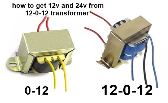
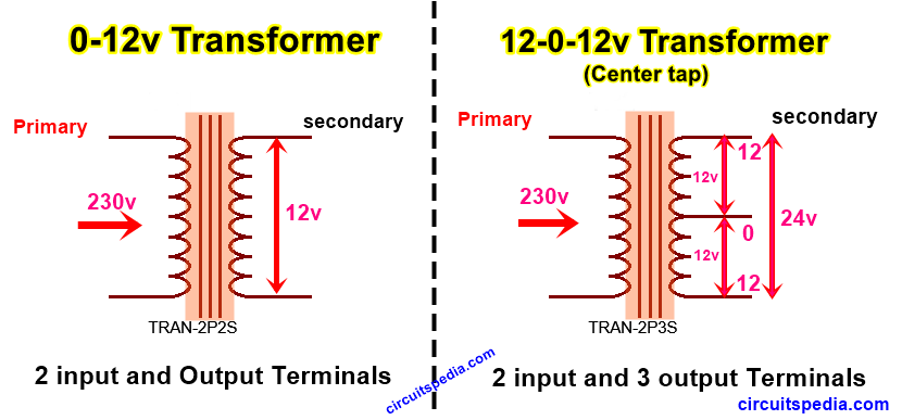
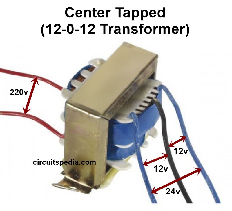
A 12-0-12 transformer is a 12v step-down transformer that has 3 terminals from secondary. This type of transformer is also called a center tap transformer. Input is 220 to 230v and output is 12v-0-12v. The middle wire terminal is considered as 0v and Each side terminal from 0v is 12v.
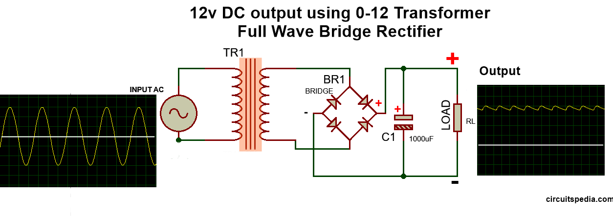
Difference between 12-0-12 and 0-12 transformer
12-0-12 transformer is 12v step-down transformer that provides two wires with 12v each and one is 0v. It has 3 output wires and this transformer also can be used for 24v supply. 12-0-12 transformer is a center-tapped transformer. 0-12 transformer is also a 12v step-down transformer but it has only 2 wires or terminal from the secondary coil. A 0-12 transformer only can be used for 12v supply whereas a 12-0-12 transformer can be used for a 24v supply.
12-0-12 transformer connection
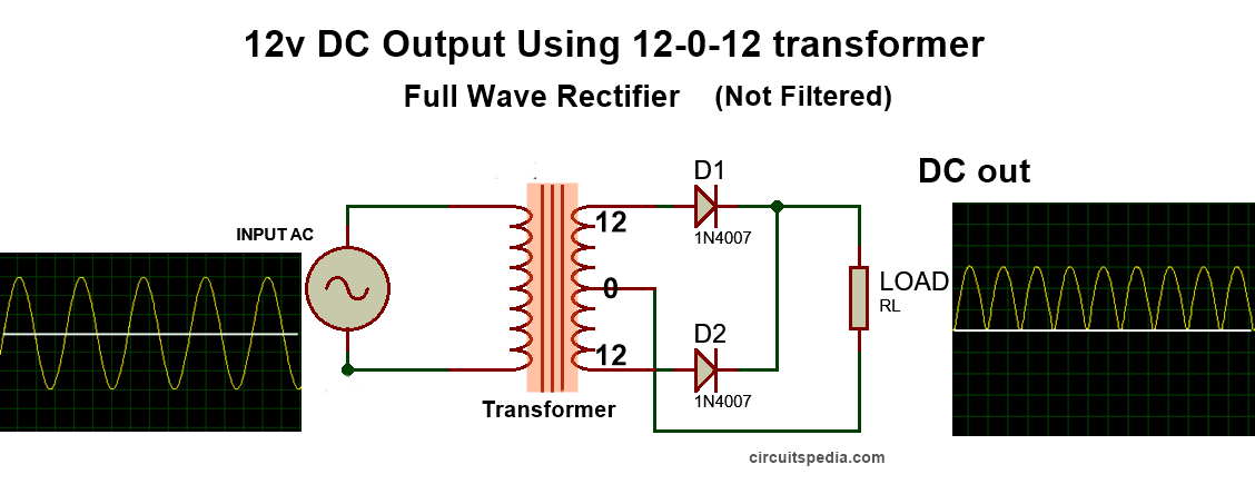
In the 12-0-12 transformer connection, we use the input 220/230v on the primary side and if we use 2 diode for full-wave rectifier then both side wires of the secondary side connect with the diode and the middle (0v) wire direct connect with the load ground or negative supply. Both wires connected with Positive Pin of Diode means AC 12v comes through the Positive terminals of diodes and output will from the negative terminal of diodes. Here DC will be Positive Output from diodes, and middle terminal of transformer directly connected for negative DC supply. This connection is used for a full-wave rectifier circuit.
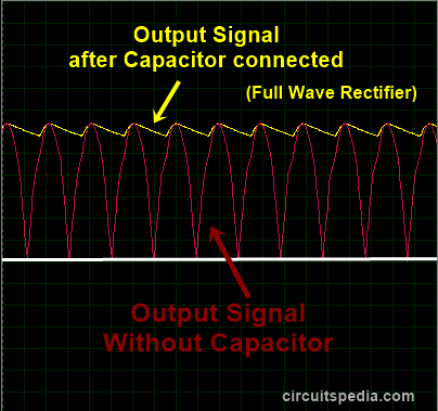
Without using capacitor Output has mush noise because not pure DC without a filter and a lot of Ripple noise not suitable for use. So use at least a 1000uF capacitor with the output for reducing the Noise. Here This connected capacitor is known as a Filter capacitor but actually this is an Electrolyte capacitor.
 12v bridge rectifier circuit
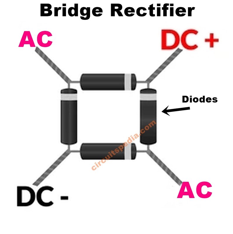
In the bridge Rectifier, 4 diodes are used and connect each other in this way two terminals of negative and two terminals of positive of diodes meet each other. Two positive terminals of diodes make a negative output pin and two negative terminals make a positive output pin. A bridge rectifier also provides full-wave rectification so it is also called full-wave rectifier.
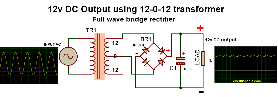
12-0-12 bridge rectifier circuit
You can use any one of the side terminals of the transformer to connect the bridge rectifier diodes along with the middle terminal. In this case, one terminal of the transformer is not connected anywhere. But in this connection, the output current will be reduced in comparison with 2 diodes full-wave rectifier connection using 0-12 transformer.
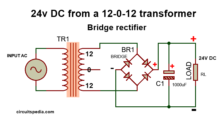
How to get 24v from a 12-0-12 transformer
For getting 24v output using a 12-0-12 transformer just connect both side terminal wires of the transformer with the diodes and keep the middle terminal of the transformer Not connected anywhere. This connection gives us a full-wave 24v output using a 12-0-12 transformer. No current will be reduced.
Note- The same method also can be applied in other center-tapped and normal step-down transformers Like 6-0-6 transformer, 9-0-9 and 15-0-15 transformers etc.
Why do we use capacitor as filters in rectification
In the rectification process, there is no full AC converted into DC, Some AC signals come without conversion and behave like Harmonic Noise or Ripple at the load section. The important property of a capacitor is to Pass only AC and Block DC, So the Unwanted AC signals are removed by the bypass across the capacitor and make the more smoother DC signal.
How we find which are primary (input) and which are secondary (output) wires/terminals of transformer–
The resistance of terminal/wires of the Primary side or input side is very very High. But Output or secondary coil side resistance is very LOW. If you measure with the continuity of a multimeter then you can hear the Beep sound. Generally, the input wires come with the RED color and Output comes with Green or Yellow, and the Middle wire is black.
Also read
- How capacitor block DC and Pass AC
- Dual power supply circuit
- AC to DC Regulated Power supply circuit
- Water level controller circuit
- Delay timer circuit
- Logic gates (AND, OR, NOR, NAND etc)

