Simple FM Transmitter Circuit
Features of This FM Transmitter Circuit
✔ Simple and cost-effective design – Uses common components like 2N2222A transistors.
✔ Decent transmission range – It covers a few hundred meters with a proper antenna.
✔ Clear audio transmission – Good frequency stability for FM signal transmission.
✔ Operates on low voltage – Can run on 9V to 12V DC power supply.
✔ Suitable for DIY projects – Ideal for beginners and electronics enthusiasts.
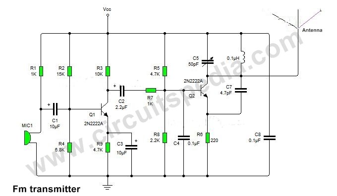
Circuit diagram of small FM Transmitter
Components and Their Functions
The circuit comprises three main sections:
1️⃣ Audio Input & Amplification Section
- MIC1 (Microphone): Captures audio signals (voice or music).
- R1 (1KΩ) & R2 (15KΩ): Provide the necessary biasing to the microphone for proper operation.
- C1 (10µF): Blocks DC components and allows only the AC audio signal to pass.
- Q1 (2N2222A Transistor): Acts as a preamplifier, amplifying the weak microphone signal.
- R3 (10KΩ), R4 (6.8KΩ), and R5 (4.7KΩ): Set the operating point (biasing) of Q1.
- C2 (2.2µF) & C3 (10µF): Coupling capacitors that smooth the amplified signal.
2️⃣ Oscillator & Modulation Section
- Q2 (2N2222A Transistor): Functions as an oscillator that generates the RF carrier wave.
- C5 (50pF) & L1 (Inductor): Work together to determine the oscillation frequency in the FM band (88-108MHz).
- C6 (0.1µF): Filters out unwanted noise and stabilizes the signal.
- R7 (1KΩ) & R8 (2.2KΩ): Provide biasing for the oscillator stage.
- C4 (0.1µF): Helps in stabilizing the oscillator circuit.
3️⃣ RF Transmission Section
- C7 (4.7pF): Couples the RF signal to the antenna for transmission.
- C8 (0.1µF): Further filters out any unwanted high-frequency noise.
- Antenna: Transmits the FM signal over the air. A simple wire or telescopic antenna can be used.
⚙️ How the Circuit Works
Step 1: Audio Signal Processing
- The microphone (MIC1) captures sound waves and converts them into electrical signals.
- This weak audio signal is amplified by Q1 (2N2222A transistor).
- The amplified signal is coupled via C2 (2.2µF) and C3 (10µF) into the next stage.
Step 2: Frequency Generation & Modulation
- Q2 (2N2222A) acts as an RF oscillator and generates a high-frequency carrier signal in the FM band.
- The amplified audio signal modulates the oscillator, varying the frequency of the carrier wave based on the audio input (FM modulation).
Step 3: Transmission via Antenna
- The frequency-modulated signal is passed through C7 (4.7pF) to the antenna.
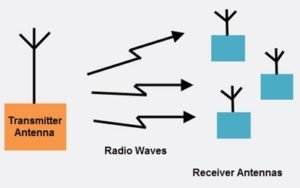
- The antenna transmits the FM signal over the air, where it can be received by an FM radio.
🔧 Optimization Tips for Better Performance
✔️ Increase Transmission Range
- Use a longer antenna (e.g., 1/4 wavelength dipole antenna).
- Improve power supply stability (use a regulated 9V-12V power source).
- Shield the circuit to reduce interference and unwanted noise.
✔️ Improve Audio Quality
- Use a high-quality microphone for clear sound capture.
- Adjust the biasing resistors (R1, R2, R3) to fine-tune amplification levels.
✔️ Stabilize Frequency
- Choose high-precision capacitors (C5, C7) and an inductor (L1) to avoid frequency drift.
- Place the circuit in a metal enclosure to prevent external RF interference.
📡 Applications of This FM Transmitter
✔ Wireless Microphone – Can be used for wireless audio transmission.
✔ Personal FM Radio Station – Useful for hobbyists and DIY enthusiasts.
✔ Remote Audio Monitoring – Can work as a small surveillance device.
✔ Wireless Music Transmission – Plays audio from MP3 players or other sources.
💡 Final Thoughts
This simple FM transmitter circuit is an effective, low-cost way to wirelessly transmit audio signals. With proper tuning and optimization, it can provide clear, stable FM transmission over a decent range.
components
- Resistors ¼ watt (220Ω-1; 1kΩ -2; 2.2kΩ; 10kΩ-1; 15kΩ; 6.8kΩ; 4.7kΩ -2)
- Electrolytic capacitors 16V (2.2µF; 10µF x 2)
- Capacitors ceramic (0.1µF x 2; 4.7pF)
- Variable capacitor (50pF)
- Inductor (0.1µH)
- Transistors (2N2222 x 2)
- Condenser mic
Working
Resistor R4 is connected to control the input RF signal to the oscillatory section. you can use a variable resistor for this.

