Introduction
What is a Mobile/Cell Phone Jammer
A cell phone jammer is a small equipment that is capable of blocking the transmission of signals between cell phones and base stations. This is mostly done by creating interference at the operating frequency ranges of cell phones, which results in no signal or significant loss of signal quality. Although cell phone jammers could be used practically anywhere, they are mainly used in areas where silence is expected or required or that areas that prohibit to use of mobile phones.
You Can Also Say Mobile Phone, Signal Blocker
Mobile Phone Jammer blocks both Receiving and transmitting signals.
• Cell phones use unique frequencies for talking and listening. Most cell phone jammers block either of the two frequencies, indirectly providing the effect of preventing of both. Cell phone jammers work on the same principles as the jammer used in preventing radio communication. They either function by disrupting the cell phone-to-base station frequencies or base-station-to-cell-phone frequencies.
• It is efficient in blocking the transmission of signals from networks including UMTS, 3G, CDMA, GSM and PHS.
• One Jammer device may not work at different frequencies because Mobile phones operate at different frequency bands in different countries.
Working of jammer circuit
Block Diagram of Mobile Jammer
For any jammer circuit, there are 5 main important circuits. When they are combined together, the output of that circuit will work as a jammer. The main circuits are
• Power Supply
• Voltage-controlled Oscillator.
• Noise Pulse Generator
• RF Amplifier.
• Tranmitting Antenna
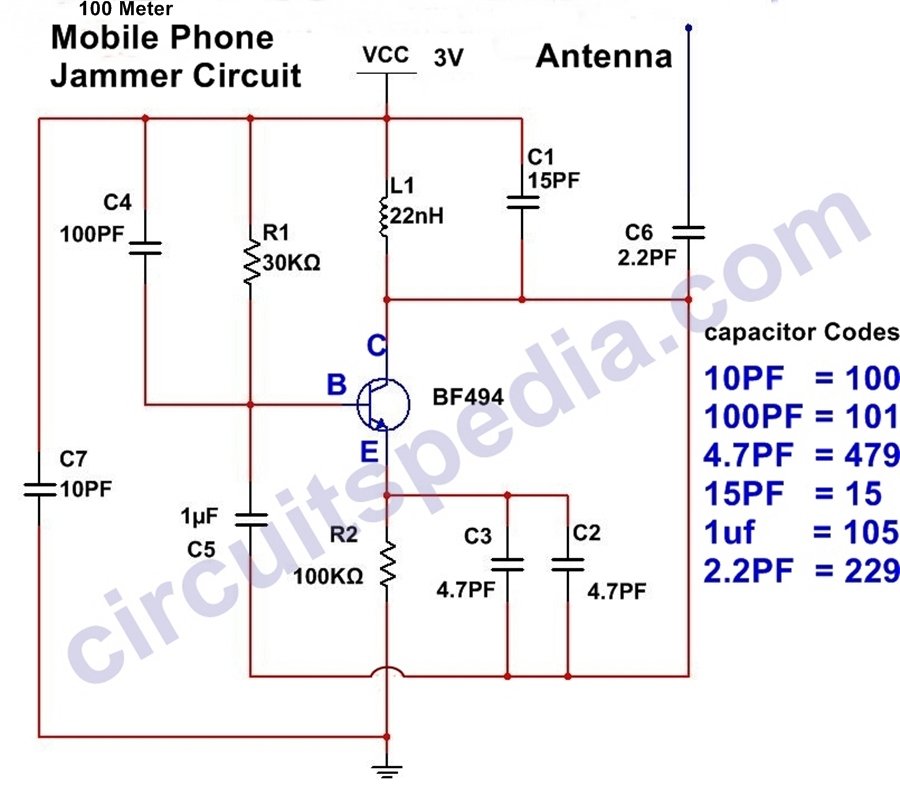
The RF amplifier circuit is created by the transistor Q1, capacitors C4 & C5, and resistor R1. This will amplify the signal generated by the tuned circuit. The amplification signal is given to the antenna through a C6 capacitor. Capacitor C6 will remove the DC and allow only the AC signal, which is transmitted in the air.
Circuit Diagram
Here, Capacitor C1 and Inductor L1 Work as frequency generators and oscillators, and the Transistor is used for Amplification.
• You can use the formula to change the frequency of circuit output depending on the frequencies you need to block; the values of the inductor (L1) and capacitor (C1) can be altered as required.
For example, if mobile phones at your area work at 450 MHz, you need to generate 450 MHz with some noise to act as the blocking signal. Now the cell phone receiver will not be able to understand which signal to receive. We have successfully blocked cell phone signals.
• Capacitor C1 and inductor L1 make a tuned circuit. This circuit acts as an oscillator with zero resistance. It produces a very high frequency with minimum damping. Both the inductor and capacitor of the tuned circuit will oscillate at their resonating frequency. When transistor Q1 is turned ON, the tuned circuit at the collector turns ON.
• The tuned circuit operation: When the circuit is ON, voltage is stored in the capacitor. After completely charging the capacitor, it allows the flow of the Charge (current) through the inductor. When current flows through the inductor, it stores magnetic energy corresponding to the voltage across the capacitor. When the charge of the inductor reaches its maximum, then the charge or voltage across the capacitor turns to Zero.
• The magnetic charge through the inductor will be decreased and the current will charge the capacitor in the opposite or reverse polarity manner. Again, after some period of time, the capacitor will get completely charged and the magnetic energy across the inductor will be completely zero. Again, the capacitor will give charge to the inductor and becomes zero. After some time, the inductor will give charge to the capacitor and become zero, and they will oscillate and generate the frequency. This process runs till internal resistance is generated and the oscillations stop.
• The capacitors C2 and C3 generate noise pulses at the tuned circuit randomly The RF amplifier boosts the frequency generated by the tuned circuit. The frequency generated by the tuned circuit and the noise signal generated by the capacitors C2 and C3 are combined, amplified, and transmitted.
The power supply should be between 3v to 5v. less than or up to 500ma
⇒ This circuit works in a small area, up to 100 meters. If the circuit is not working, just increase the resistor and capacitor values in the circuit. Increase the frequency of the tuned circuit by using the formula that is given in this article.
Please do not Use This For Unnecessary things. It may illegal
Also Read
- Switch ON delay Timer
- Electronics MCQ question answers(Quiz)
- Dark sensor circuit for automatic ON-OFF
- LED chaser/Flasher circuit
- Fan Regulator/AC dimmer
- How capacitor block dc current
- Active, Passive, Linear, Non-Linear, Unilateral, Bilateral Elements


I think the admin of this website is really working hard in support of his site, for the reason that here every information is quality based information.
sir Iti electronic 4th samester drawing pata nhi chal Raha h
What is the replacement of inductor
This is a fascinating post! I had no idea how mobile phone jammers worked until now. The circuit diagram is really helpful for visualizing the concept. I appreciate the detailed explanation and am eager to learn more about the applications and legal aspects of using phone jammers. Keep up the great work!
This is a fascinating read! The circuit diagram you provided is quite helpful for understanding how a mobile phone jammer works. I appreciate the detailed explanation of the components involved. Looking forward to more articles on similar topics!