Remote controlled AC Load With Arduino Without Relay
Arduino remote control
Here, I am presenting a mini project of a remote control switch for any AC appliance without Relay. A homemade Arduino Remote control switch is an interesting idea. Arduino Uno board is used here, but you can use any Arduino board.
Download Arduino Library Proteus
Generally, Coil Relays are used to control ON-OFF to any appliance. These coil relays have mechanical moving contact pins for switching. But when using TRIAC, then no need to use that relay. Using the TRIAC and Optocoupler makes a Different type of Relay called Solid state relay. In a solid-state relay circuit, there are no moving parts components are used. Here optocoupler IC is used As an isolator to isolate the AC signal from other DC circuits. An optocoupler IC is a type of IC that has an IR LED and a phototransistor or phototriac internally. IR LED is used to activate the phototransistor or phototriac For Triggering to Triac for switching.
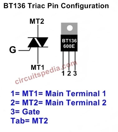
Here, the Optocoupler MOC3021 is used. For one Load One optocoupler and one Triac used separately so, if you want to connect 10 Load then you need 10 MOC3021 ICs and 10 Triac. You can use any Triac of BT134 or BT136 or BT139. BT139 has a maximum load capacity of 9A. BT136 has 6A and BT134 has 4A maximum Load capacity.
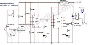
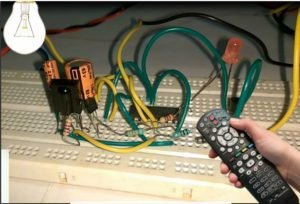
Any IR remote control you can use for this, like a TV, DVD, Music Player Remote, etc. The only thing is that the Program must be as your remote because the coding signal of each remote may be different. Here, I use only 5 bulbs as load with the circuit, but 12-13 bulbs can be connected. This circuit can be used to switch ON or OFF any 12-13 AC Appliance using a Remote with 8-10 meter distance. The TSOP 1738 IR detector is used to receive the IR signals transmitted from the remote.
Arduino IR remote
Components required
TRIAC BT136 or 139 (5 Pcs for 5 Load)
Optocoupler IC MOC3021 (5 for 5 Load)
Resistors
470Ω-5
220Ω-5
IR sensor TSOP1738 or HS0038-1
Arduino UNO board
schematic diagram
Step 1 : Download the Arduino-IR remote-2.1.0 zip file
Step 2 : Open Arduino (Arduino IDE)
step 3 : Go to Sketch⇒ Include Library⇒ Add.ZIP library
Step 4 : Select your file and click enter
IR sensor Arduino code
♦ How to Decode IR Signal of the Remote For the Program
Copy the following code and paste and then verify and upload to Arduino board
#include <IRremote.h>
int RECV_PIN = 3;
IRrecv irrecv(RECV_PIN);

decode_results results;

void setup(){
  Serial.begin(9600);
  irrecv.enableIRIn();
}

void loop() {
if (irrecv.decode(&results)) {
    Serial.println(results.value, DEC);
    irrecv.resume();
  }
}

 Go to   Tools⇒ Serial Monitor
Then a blank page opened
Now press the key one by one (which keys you want to use) for instantly. You will see some coded values for each key.

Components
Arduino UNO – (buy–https://amzn.to/2OvDn6A)
Optocoupler MOC3021-5 pc (buy–https://amzn.to/2OvDn6A)
Triac BT136-5 pc (buy–https://amzn.to/2vUpDvV)
Resistor 470 ohm- 5 pc (buy–https://amzn.to/2Ouz2AG)
Resistor 220 ohm- 5 pc (buy–https://amzn.to/31uJ8H5)
TSOP1738 sensor (buy–https://amzn.to/2OwKLP4)
IR sensor Arduino program
Then open the new file and copy and paste the following program
Note- Decoded Value of Your Remote may differ from this value
#include <IRremote.h>
#define irPin 3
IRrecv irrecv(irPin);
decode_results results;
#define  L1 4
int Load1 = LOW;
#define L2 5
int Load2 = LOW;
#define L3 6
int Load3 = LOW;
#define L4 7
int Load4 = LOW;
#define L5 8
int Load5 = LOW;

void setup()
{
irrecv.enableIRIn();
pinMode(L1, OUTPUT);
pinMode(L2, OUTPUT);
pinMode(L3, OUTPUT);
pinMode(L4, OUTPUT);
pinMode(L5, OUTPUT);

}
void loop() {
if (irrecv.decode(&results)) {
switch (results.value) {


case  3772784863 :
Load1 = ~ Load1;
digitalWrite(L1,Load1);
delay(300);
break;
case 3772817503 :
Load2 = ~ Load2;
digitalWrite(L2,Load2);
delay(300);
break;
case 3772801183 :
Load3 = ~ Load3;
digitalWrite(L3,Load3);
delay(300);
break;
case 3772780783 :
Load4 = ~ Load4;
digitalWrite(L4,Load4);
delay(300);
break;
case 3772813423 :
Load5 = ~ Load5;
digitalWrite(L5,Load5);
delay(300);
break;

case 3772793023 :
Load1= ~ Load1;
digitalWrite(L1,Load1);
Load2= ~ Load2;
digitalWrite(L2,Load2);
Load3= ~ Load3;
digitalWrite(L3,Load3);
Load4= ~ Load4;
digitalWrite(L4,Load4);
Load5= ~ Load5;
digitalWrite(L5,Load5);
delay(300);
break;

case  3772811383 :
digitalWrite(L1,0);
digitalWrite(L2,0);
digitalWrite(L3,0);  // all off
digitalWrite(L4,0);
digitalWrite(L5,0);
delay(300);

break;

}

irrecv.resume();
}
}






Hi Aman !!!
How are you ? hope you are fine
Aman I need the matterials related with the above project and plz share Coding and simulation with me on mail.
Will be your indebted alot.
ijazwazir94@gmail.com