Dark/Light Activated Circuit using LDR
A light-activated triac circuit automatically powers an AC load (like a bulb) when it detects low ambient light levels. Unlike relay-based designs, this circuit uses a triac for switching, eliminating the need for mechanical parts. As a result, it operates quietly and can switch AC loads efficiently. The core sensing element is an LDR (Light light-dependent resistor) whose resistance changes according to the amount of light.
Components
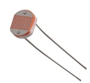
LDR (Light Dependent Resistor)
- Changes resistance based on light intensity.
- Lower resistance in bright light, higher resistance in darkness.
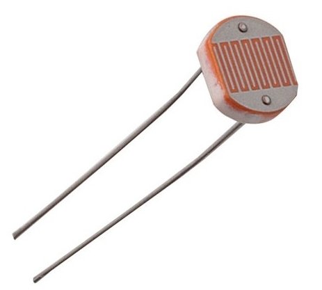
An LDR (Light light-dependent resistor) is a special resistor whose resistance changes based on the intensity of light falling on it. When it’s bright, the LDR’s resistance becomes low, allowing more current to pass through. In darkness or low light, its resistance rises significantly, limiting current flow.
This behavior is typically due to the photoconductive material (often cadmium sulfide) used in the LDR. Under bright light, more free charge carriers (electrons) are generated within the material, reducing its electrical resistance. In darkness, fewer carriers are available, so the resistance increases.
An LDR (Light light-dependent resistor) is a special resistor whose resistance changes based on the amount of light falling on it. In bright light, the LDR’s resistance becomes low, allowing more current to flow. In darkness or low light, its resistance becomes very high, allowing little current to flow. This property makes LDRs ideal for sensing and reacting to changes in ambient light levels, such as in automatic night-light circuits or camera light meters.
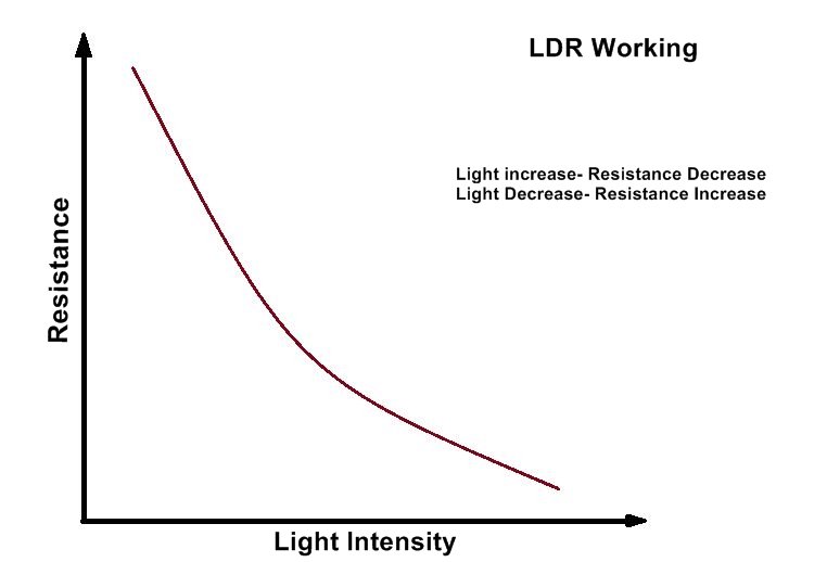
In circuits, LDRs are usually placed in voltage divider configurations or sensor inputs. As the light level changes, the LDR’s resistance shifts the voltage or current at certain nodes in the circuit, enabling the detection of day/night conditions or variations in light intensity—essential for applications like automatic night lights, brightness controls, and alarm systems.
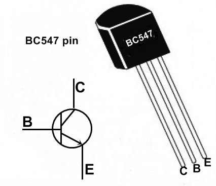
Transistor (Q1 – BC547B)
- A general-purpose NPN transistor.
- Used to amplify the small current from the LDR/pot network and drive the triac’s gate.
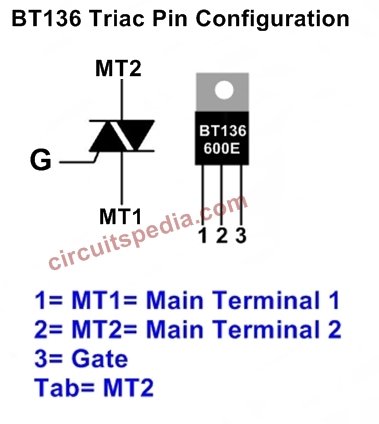
Triac (BT136 or similar)
- A bidirectional semiconductor switch for AC loads.
- Conducts current in both half-cycles of the AC waveform once triggered.
Preset Potentiometer (100 kΩ)
- Adjusts the switching threshold of the circuit.
- Lets you fine-tune the light level at which the lamp turns on.
Resistor (R1 = 1 kΩ)
-
-
Limits current from the transistor’s collector to the triac’s gate.
-
Power Supply (±12 V DC)
- The circuit in the diagram shows a +12 V rail and a -12 V (or ground) rail.
- Used to power the transistor and LDR network.
- The triac side is connected to 230 V AC for the load.
AC Load (Lamp, X1)
- A typical incandescent or LED bulb rated for 230 V (or the local mains voltage).
- Switched by the triac when darkness is detected.
Circuit Diagram Overview
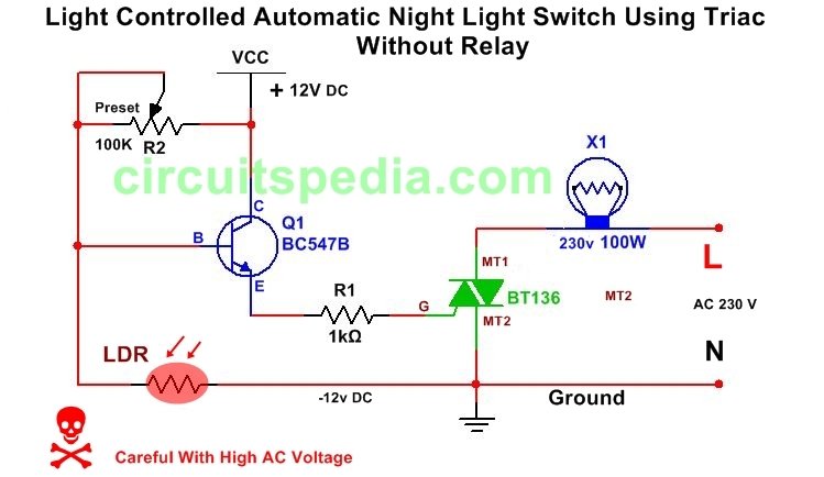
From the uploaded schematic, you’ll notice:
- A preset (100 kΩ, R2) and an LDR form a voltage divider at the base of Q1 (BC547B).
- The collector of Q1 is connected to the gate of the triac (BT136) through a 1 kΩ resistor (R1).
- The emitter of Q1 going to the negative rail (-12 V) or ground reference.
- The triac’s MT1 (Main Terminal 1) is connected to the neutral or ground reference in some designs, while MT2 goes to the load, which is then connected to the live AC line (or vice versa, depending on local wiring conventions).
This arrangement ensures that the transistor drives the triac gate, controlling current flow to the lamp.
Power Supply and Voltage References
±12 V DC Supply
- Although the circuit shows a “+12 V” and “-12 V” labeling, in many practical builds, you might have a single 12 V supply with ground as the negative rail.
- The essential requirement is that the transistor and LDR network have a stable DC source.
- Ensure the ground (or negative terminal) is referenced properly so that the transistor can switch correctly.
AC Mains
- The triac side of the circuit is connected to 230 V AC (or local mains voltage).
- One terminal of the lamp (load) goes to the AC live line, and the other terminal goes to the triac’s MT2. MT1 (or the triac’s other main terminal) is often connected to neutral or ground.
- Always follow local electrical codes and use caution when dealing with high voltage.
How the LDR Controls the Transistor
An LDR and a preset potentiometer (100 kΩ) form a voltage divider:
- In bright light, the LDR’s resistance is low. The base of Q1 sees a lower voltage, keeping Q1 off.
- In darkness, the LDR’s resistance increases. The voltage at the transistor’s base rises, eventually turning Q1 on.
By adjusting the potentiometer, you set the point at which Q1 starts to conduct as the ambient light changes.
Triac Switching
Triac Basics
A triac (Triode for Alternating Current) is a semiconductor that:
- Allows current to flow when its gate receives a triggering current.
- Continues to conduct until the AC waveform crosses zero or the current drops below a certain threshold.
Gate Drive via the Transistor
- When the transistor conducts, a small current flows from the collector through the 1 kΩ resistor (R1) into the triac gate.
- This triggers the triac, letting current flow from MT2 to MT1 (or vice versa, depending on the wiring) and powering the load (lamp).
- The lamp remains lit until the transistor stops driving the gate (when it’s bright again) and the AC current crosses zero.
Step-by-Step Working Principle
Daylight (High Ambient Light)
- LDR resistance is low.
- Base voltage of Q1 is too low to forward-bias the transistor.
- Q1 is off → No gate current to the triac → Lamp is off.
Dusk (Decreasing Light)
- LDR resistance increases.
- The base of Q1 gradually sees a higher voltage.
- At a certain threshold (set by the 100 kΩ preset), Q1 starts to conduct.
Night (Darkness)
- LDR resistance is high.
- Q1 base is fully biased → Q1 saturates (fully on).
- Current flows into the triac gate → Triac conducts → Lamp turns on.
Return to Day
- Light intensity increases again → LDR resistance drops.
- The base of Q1 no longer gets enough voltage to keep it saturated.
- Q1 turns off, no gate current → Triac stops conducting at the next AC zero crossing → Lamp goes off.
Circuit Construction and Connections
Mounting and Layout
- Use a small PCB or breadboard to test the transistor and LDR arrangement.
- Keep high-voltage connections (the triac and lamp) physically separate from the low-voltage control section for safety.
Transistor and Resistors
- Ensure correct pin orientation for the BC547B (E-B-C).
- The 1 kΩ resistor from collector to triac gate must be adequately rated to handle any brief surge current.
Triac
- The triac (BT136 or similar) should be placed on a heat sink if the load is high-wattage.
- Ensure correct identification of MT1, MT2, and Gate pins (check datasheet or package markings).
LDR Placement
- Position the LDR where it can accurately sense ambient light changes (e.g., near a window or outdoors in a protected enclosure).
- If you’re using this outdoors, shield the circuit from moisture, but leave the LDR exposed to light.
AC Wiring
- One side of the lamp goes to the live AC line.
- The other side of the lamp goes to triac MT2.
- Triac MT1 typically goes to the neutral or ground reference (depending on local wiring norms).
Adjusting the Sensitivity
The 100 kΩ preset (potentiometer) allows you to set the exact point at which the lamp turns on:
- Power On the circuit with the lamp connected.
- Dim the Lights or wait until evening.
- Turn the preset until the lamp just switches on at the desired level of darkness.
- Fine-Tune further if you want the lamp to come on earlier or later in the evening.
This adjustment ensures you get precise control over the ambient light threshold.
Applications and Benefits
- Street Lighting: Turns on automatically at dusk, off at dawn.
- Garden/Landscape Lighting: Ideal for outdoor areas that need illumination only at night.
- Security Lights: Improves safety by automatically lighting entrances or driveways.
- Energy Savings: Prevents lights from running during daylight, reducing electricity costs.
- No Mechanical Parts: Triac-based switching is silent and durable compared to relay-based designs.
Safety Precautions
High Voltage Alert
- Parts of this circuit connect directly to 230 V AC (or local mains).
- Always ensure proper insulation and fuse protection.
Proper Grounding
- The circuit reference (negative rail) must be clearly identified if used in conjunction with the AC neutral.
- Avoid accidental shorts or reversed connections.
Heat Management
- If driving a high-wattage load, the triac may need a heat sink.
- Monitor temperature during initial testing.
Component Ratings
- Choose a triac rated above your load’s maximum current.
- Use resistors with appropriate wattage ratings (1/4W is typically fine for the control side).
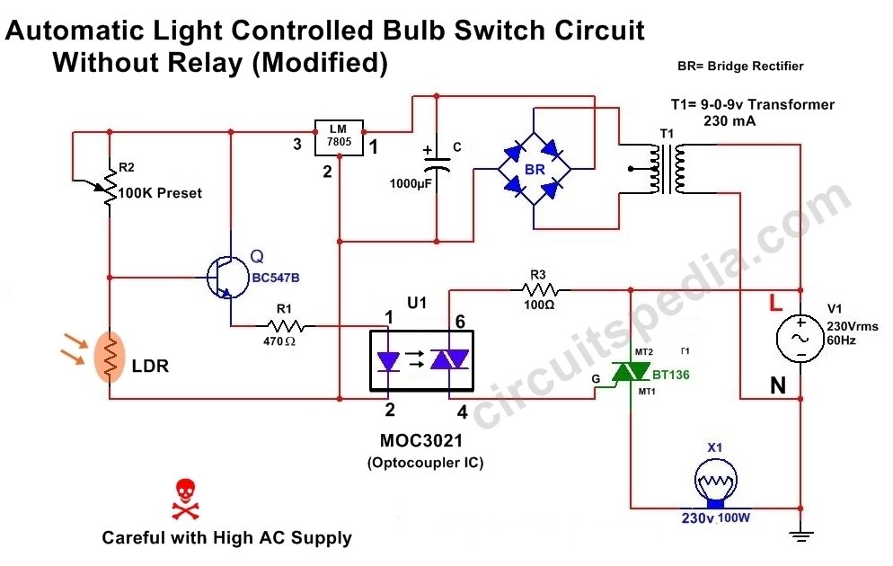
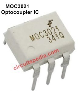
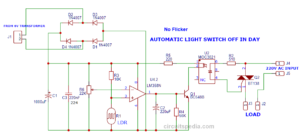
Here is a modified circuit diagram of the Automatic Light Operated bulb switch. In this circuit, an Optocoupler IC MOC3021 is used. This Optocoupler isolates the High AC voltage from the whole circuit. Then, this circuit is isolated from the High AC current. Only Triac and some portion of the circuit flows AC supply. Now, this is more Protected and less dangerous than the first circuit.
This is an automatic Light operated Bulb Switch circuit using LDR, Optocoupler, and TRIAC.



i would like to ask for help, my optocoupler had only 4 legs and 1 pair is cathode anode for the diode part and other is Emitter and collector.
Collector acts as the output while the other 3 as input. i would like to ask for sample circuits i can make use to ensure my optocoupler is working right
Your Optocoupler may be PC817 or MCT2E or 4N35. These optocouplers has internally light-activated transistors and these do not use for controlling direct AC. You Must use MOC3021/3022 or other this type of optocouplers. This optocoupler has an internal optoTriac and two pins of these can directly be connected to control the AC.