Dual power supply circuit
Some circuits require dual power for better operation, like a power amplifier, audio amplifier, or another power circuit. Those circuits made for operating with dual supply input voltage.
What is a Dual Power Supply?
A dual power supply is an electrical circuit that provides two voltage outputs, typically one positive and one negative with respect to a common ground. It is widely used in applications requiring both positive and negative voltage levels, such as operational amplifiers, audio amplifiers, and analog circuits.
How Does a Dual Power Supply Work?
A dual power supply converts AC voltage from a transformer into two DC voltage levels using rectifiers, filters, and voltage regulators. The basic process involves:
- Step-Down Transformer: Reduces high AC voltage to a lower AC voltage.
- Rectification: Converts AC voltage into pulsating DC using a bridge rectifier (diodes).
- Filtering: Smooths out the pulsating DC using capacitors.
- Regulation: Provides a stable dual voltage output using voltage regulators like 7812 (for +12V) and 7912 (for -12V).
Applications of Dual Power Supply:
- Operational Amplifiers (Op-Amps) – Used in signal processing circuits.
- Audio Amplifiers – Powering speaker driver circuits.
- Medical Equipment – Used in precision monitoring devices.
- Embedded Systems – Powering microcontrollers requiring dual voltage levels.
- Analog and Digital Circuits – Required in mixed-signal applications.
Common Dual Power Supply Voltages:
-
±5V, ±12V, ±15V, ±24V (depending on application requirements).
Dual supply means- One terminal gives +ve. One terminal gives -ve, and one is for ground.
Two terminals give +ve and -ve supply accordingly, and the third is grounded,
For example, if any circuit requires a 12v dual supply, that means it needs three input: 1 is +12v, 2 is -12v and 3 is Ground.
Here, I am giving some circuits of dual power supply with regulated and non-regulated output.
• Center-tapped transformer is best for dual power supply circuits. It means the primary (input)has 2 terminals, and the secondary (output) has 3 terminals.
Select the diode for the rectifier as per the ampere required. You can use a ready-made bridge rectifier IC, which is available in the market with different current ratings.
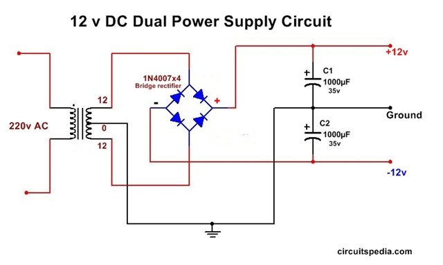
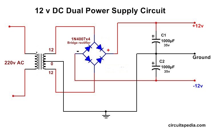
12v dual power supply Circuit (Unregulated)
This is the general 12 V DC Dual power supply circuit. The output is not regulated of this circuit
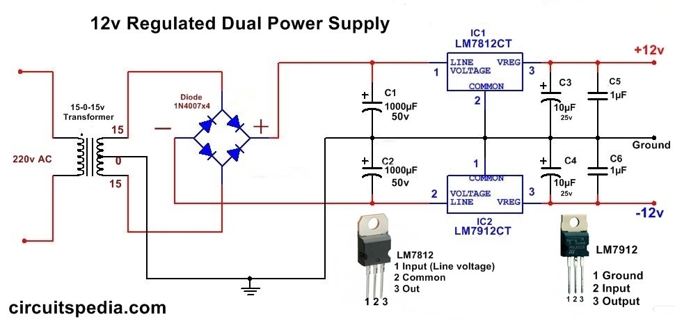
The following circuit diagram gives regulated dual power output, A Regulator ic is used in these circuits.
12v dual power regulated supply circuit
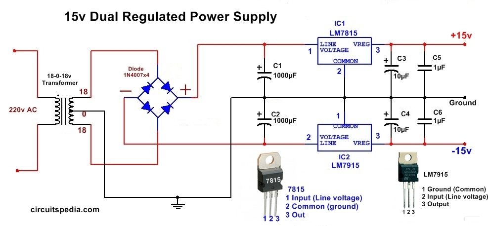
Dual 15v Regulated Power Supply
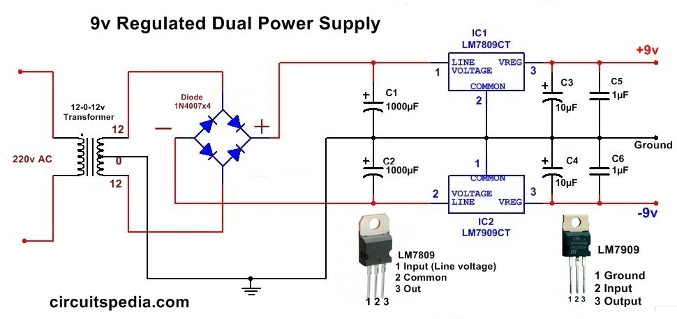
9V dual Regulated power supply circuit
• 79xx ic is used to regulate the negative input voltage where as the 78xx ic is used for positive input dc voltage regulation.
• Capacitor value can be used between 1000uf to 4700uf
• The pin configuration of LM 78xx and LM79xx are not the same so careful when connecting.
• The minimum input voltage should be greater than 3 volts than the required output if you use a regulator IC. But if not ic used in the circuit then the same voltage transformer used as output is required.
Also read
-
Variable voltage regulator using LM317
-
Overvoltage and undervoltage protection circuit
-
Zener diode working
-
Stabilizer Circuit Diagram
-
Automatic Light Activated Bulb Switch Controller
-
What is DIAC


I wish to tank you for your wonderful work done.