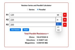
Open circuit and Under Load Voltage divider calculator
Voltage Divider Calculator
Load Calculations
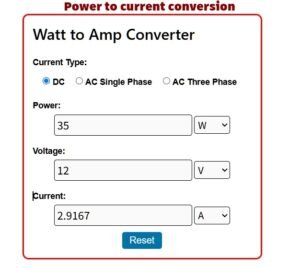
Also try–Watts to Amps (Power to Current Converter)

What is a Voltage Divider?
A voltage divider is a simple circuit that divides an input voltage into smaller output voltages using resistors. It’s one of the most commonly used circuits in electronics, found in sensors, amplifiers, and signal conditioning systems.
The voltage divider rule is a fundamental principle in electronics that explains how voltage is distributed across resistors in a series circuit. It helps determine the output voltage taken across one of the resistors when an input voltage is applied.
Basic Concept
- A voltage divider consists of two or more resistors connected in series.
- The input voltage (Vin) is applied across the entire resistor network.
- The output voltage (Vout) is measured across one of the resistors.
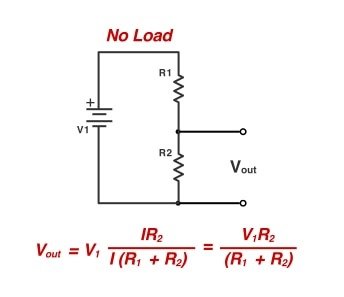
Basic Voltage Divider Circuit
A typical voltage divider consists of two resistors connected in series across a voltage source. The output voltage is taken across one of the resistors.
- Vin = Input voltage
- R1, R2 = Resistors
- Vout = Output voltage (taken across R2)
The Voltage Divider Formula
The voltage divider rule states that the voltage across a resistor in a series circuit is proportional to its resistance compared to the total resistance.
The formula for the output voltage (Vout) is:
Where:
- Vout = Output voltage across R2
- Vin = Input voltage
- R1, R2 = Resistor values
How the Formula Works
Total Resistance (R_total) – Since R1 and R2 are in series, their resistances add up:
Current (I) in the Circuit – Using Ohm’s Law, the current flowing through the resistors is:
Voltage Drop Across R2 – The output voltage is the voltage across R2, which is:
This gives us the voltage divider formula!
Practical Example of a Voltage Divider
Let’s say we have:
- Vin = 9V
- R1 = 3kΩ
- R2 = 6kΩ
Using the voltage divider formula:
So, the output voltage across R2 is 6V.
Applications of Voltage Dividers
Voltage dividers are used in many electronic applications, including:
- Potentiometers (Variable Resistors) – Adjusting volume in audio devices.
- Sensor Circuits – Converting resistance changes (e.g., thermistors, LDRs) into measurable voltages.
- Biasing Transistors – Setting proper voltage levels in amplifier circuits.
- Level Shifters – Reducing voltage for microcontrollers (e.g., 5V to 3.3V conversion).
- Reference Voltage Generation–Provides stable reference voltages for analog circuits (e.g., comparators, ADCs).
- Zener Diode Voltage Regulation– Works with Zener diodes to create regulated voltage supplies.
Limitations of Voltage Dividers
While voltage dividers are useful, they have some limitations:
- Loading Effect – If a load (like a microcontroller) is connected to Vout, it draws current and alters the output voltage. To minimize this, the load resistance should be much larger than R2.
- Power Dissipation – High resistor values reduce power loss but may increase noise sensitivity.
- Fixed Ratios – Voltage dividers provide a fixed ratio unless variable resistors are used.
Tips for Designing Voltage Dividers
- Choose Appropriate Resistor Values – Too low values waste power; too high values make the circuit noise-sensitive. A good range is between 1kΩ and 100kΩ.
- Account for Load Resistance – Ensure the load doesn’t significantly affect the output voltage.
- Use Precision Resistors – For accurate voltage division, use resistors with low tolerance (e.g., 1% or 0.1%).
Conclusion
The voltage divider rule is a simple yet powerful tool in electronics. By understanding how resistors divide voltage, you can design circuits for sensors, signal conditioning, and more. Remember the formula:
With this knowledge, you can confidently analyze and build voltage divider circuits for your projects.
The voltage divider rule is essential for designing circuits involving sensors, voltage scaling, and biasing. Engineers and hobbyists can easily calculate output voltages in resistive networks by using the simple formula Vout = Vin × (R₂ / (R₁ + R₂)).
FAQs
Q1: Can I use more than two resistors in a voltage divider?
Yes! For multiple resistors, the formula extends to:
where Rx is the resistor across which you measure Vout.
Q2: Why does a voltage divider fail under heavy load?
If the load resistance is too low, it draws excess current, altering the voltage division ratio.
Q3: Can I use capacitors or inductors in a voltage divider?
Yes! AC voltage dividers use capacitors (capacitive dividers) or inductors (inductive dividers) for frequency-dependent applications.
By mastering the voltage divider rule, you unlock a key concept in electronics that’s essential for circuit design and analysis. Happy building!
Image source- digikey.in
More Tools-


