Homemade Long-Range 1 W FM Radio Transmitter Circuit
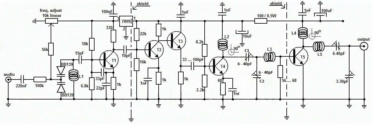
A transmitter circuit that produces frequencies between 88 to 108 MHZ should be good in quality in respect of good transmitting capability with a good area covering. This FM transmitter can cover up to 5 km area with stable frequency quality. The reason for the use of the voltage regulator 7809 is to regulate the voltage power supply for the stability of transmission Frequency. If even some fluctuation of power supply remains, then oscillation may change and then output power affects. Adjustment is achieved by using the 10K linear potentiometer. The output power of this long-range RF transmitter is around 1W but can be higher if you use transistors like KT920A, BLX65, BLY81, 2N3553, 2SC1970, or 2SC1971. This is Long-range, very stable, harmonic-free. The circuit of this project is a little hard but can be built if we work carefully with it.
Key Features of the FM Transmitter Circuit
-
Long-distance transmission: With proper tuning and a good antenna, it can transmit signals several kilometers away.
-
Stable frequency operation: Uses varicap diodes and shielded sections to minimize frequency drift.
-
High-quality audio transmission: Ensures clear modulation without excessive distortion.
-
Multiple amplification stages: Uses several transistor-based amplifiers to strengthen the signal progressively.
-
Frequency adjustability: Includes variable capacitors to fine-tune transmission frequency.
-
Efficient power usage: Incorporates a 7809 voltage regulator to maintain consistent opera
Two varactor diodes act like a variable capacitor when you adjust the pot to adjust the frequency. A Varactor Diode is a reverse-biased p-n junction diode whose capacitance can be varied electrically. As a result, these diodes are also referred to as varicaps, tuning diodes, voltage variable capacitor diodes, parametric diodes, and variable capacitor diodes.
By varying the diode capacitance, the L1 + diodes circuit makes a resonance circuit for T1. use the 10k linear potentiometer like this: if you trim down, towards the ground, the freq. will drop, and if you adjust it toward + it will rise. Basically, the potentiometer is used as a variable power supply for the two BB139 varicap diodes .T1 is used as an oscillator stage to deliver a low-power stable frequency. You can use transistors like BF199, BF214, but do not use BCs. At this moment, you don’t have the long-range FM transmitter because the power is quite low, no more than 0.5 mW.T2 and T3 works as a buffer stage, T2 as a voltage amplifier, and T3 as a current amp. This buffer stage is very important for freq stabilization because is a tampon circuit between the oscillator and the preamp and final amplifier.
🛠️ Circuit Components & Their Functions
This circuit consists of various active and passive electronic components that work together to generate, modulate, amplify, and transmit the FM signal effectively. Below is a breakdown of the major components and their roles in the circuit.
1️⃣ Audio Input & Frequency Modulation Section
- Audio Input: The circuit receives an audio signal from a microphone or external source.
- Varicap Diodes (BB139): These voltage-controlled diodes alter capacitance to modulate the carrier frequency based on the audio input.
- Inductor (L1): Works with capacitors to form the oscillator circuit, generating an FM carrier wave in the VHF band.
- Biasing Resistors (56kΩ, 6.8kΩ, etc.): Provide the required DC bias to ensure proper operation of transistors.
2️⃣ Oscillator & Buffer Amplification (T1, T2, T3 Stages)
- T1 (Oscillator Transistor): Generates the initial high-frequency carrier wave, which is later modulated with the audio signal.
- Capacitors (15pF, 33pF, 22pF, etc.): Form part of the tank circuit, determining the oscillation frequency.
- T2 & T3 (Buffer Amplifiers): Prevent loading effects on the oscillator and isolate the frequency-modulated signal before power amplification.
3️⃣ Power Amplification Stage (T4 & T5)
- T4 (Pre-Amplifier): Boosts the modulated signal before final power amplification.
- T5 (Final RF Power Amplifier): Increases the signal strength for long-distance transmission.
- L3, L4, L5 (Inductors): Act as RF chokes, improving efficiency by matching impedance and filtering noise.
- Capacitors (6-40pF, 3-30pF): Used for fine-tuning and signal stabilization in the output stage.
4️⃣ Power Supply & Voltage Regulation
- 7809 Voltage Regulator: Provides a stable 9V power supply, ensuring consistent circuit performance.
- 100µF & 1nF Capacitors: Filter unwanted power fluctuations to maintain a clean signal.
5️⃣ Antenna & Transmission Section
- Output Section: The final amplified RF signal is transmitted via the antenna.
- Antenna Matching Network (Capacitors & Inductors): Ensures efficient signal radiation by matching impedance with the transmission frequency.
⚙️ How the Circuit Works – Step-by-Step Explanation
Step 1: Audio Signal Processing & Modulation
- The input audio signal (voice or music) is applied to the circuit.
- The BB139 varicap diodes modulate the carrier frequency according to the input signal.
- The oscillator circuit (T1, L1, capacitors) generates a high-frequency FM carrier wave.
Step 2: Signal Isolation & Buffer Amplification
- The buffer amplifier stages (T2 & T3) isolate the oscillator from power amplifier sections.
- This step prevents frequency fluctuations and signal distortion.
Step 3: RF Power Amplification
- The modulated signal is gradually amplified using T4 and T5 transistors.
- The impedance-matching network (L3, L4, L5) enhances power transfer to the antenna.
Step 4: Transmission via Antenna
- The final high-power FM signal is transmitted via the antenna.
- Proper impedance matching ensures maximum range and efficiency.
🔧 Optimization Tips for Better Performance
✔️ Improve Transmission Range
- Use a tall, properly tuned antenna (e.g., a 1/4-wave ground plane antenna).
- Increase transmitter power by optimizing the final RF amplifier stage.
- Minimize interference by shielding sensitive circuit sections.
✔️ Enhance Signal Stability
- Ensure a stable 9V power supply using a high-quality 7809 regulator.
- Use high-precision capacitors and inductors to prevent frequency drift.
- Shield oscillator and RF stages to reduce external signal interference.
✔️ Improve Audio Quality
- Use a low-noise microphone or audio source.
- Adjust the modulation depth by fine-tuning the BB139 varicap diodes.
- Maintain proper impedance matching between audio, RF, and antenna sections.
📡 Applications of the Long-Range FM Transmitter
✔ FM Broadcasting: Used in local FM radio stations for community communication.
✔ Wireless Audio Transmission: Can transmit audio from a music player or microphone wirelessly.
✔ Surveillance & Security: Used in covert operations for remote audio monitoring.
✔ Ham Radio & Experimentation: Popular among RF enthusiasts and electronics hobbyists.
💡 Final Thoughts
This long-range FM transmitter circuit is a high-performance wireless communication system capable of transmitting clear, stable FM signals over long distances. It features multiple amplification stages, frequency stabilization, and impedance matching for maximum efficiency.
By optimizing antenna design, power supply stability, and component selection, you can enhance range and signal quality for professional-grade FM transmission.
RESISTOR CAPACITOR
56k 1 100uf 1
100k 1 10uf 1
18k 1 220nf 1
6.8k 1 15pf 1
330om 1 100nf 1
1k 4 22pf 1
22k 1 10pf 1
8.2k 1 1nf 5
10k 1 100pf 1
2.2k 1
68Ω 1
100Ω 1w 1
Variable(PRESAT LINEAR) 10k 1
variable capacitor(TRIMMER)
40pf 3
30pf 1
Diode (varicap)
BB139 2
Transistor
T1 = T2 = T3 = T4 = BF199
T5 = 2N3866, 2N4427 or 2SC1970 for 1Watt / 2SC1971, BLX65, BLY81, KT920A or 2N3553 for 1.5 to 2W power.
L1 = 5 turns / 0.6mm / 4mm silvered copper
L2 = 6 turns / 0.8mm / 6mm enameled copper
L3 = 3 turns / 1mm / 7mm silvered copper
L4 = 6 turns / 1mm / 6mm enameled copper
L5 = 4 turns / 1mm / 7mm silvered copper
Also read Basic concepts of PN junction Diode
Also Read DC Motor/Fan Speed Controller circuit
reference www.electronics-diy.com/

