Remote controlled switch for Appliance
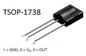
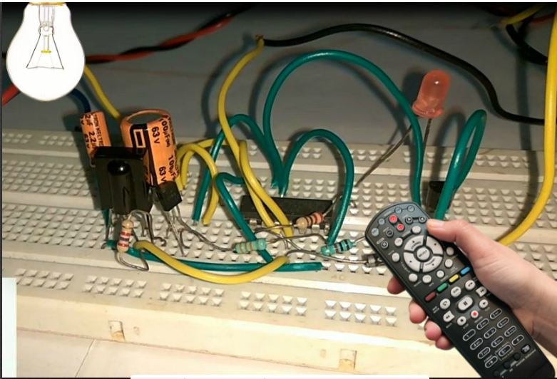
A switch that is place in your hand at bed, this is controlled wireless to operate an appliance. Which is so unique for whose who use conventional switch to switch or off his appliance at your home. A remote-controlled switch that can ON or OFF any appliance using a TV, DVD or DTH remote. This remote controlled switch project is based using TSOP 1738 sensor, TSOP 1738 is a infrared (IR) ray receiver. TSOP 1738 is an IR sensor that is used for receiving the Infrared signal from any remote.
Construction
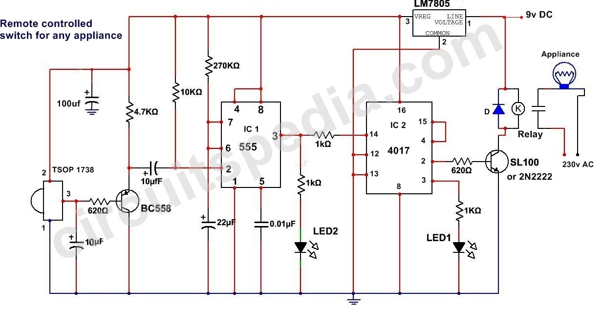
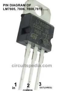
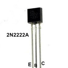
Output pin of Sensor is connected with the base of a PNP transistor. The emitter pin of this transistor is connected with the capacitor and its negative terminal is connected with the trigger pin of IC1 555. Pin 1of sensor is connected with ground and pin 2 is connected with the supply input voltage. A 5 v Regulator(7805) is connected to regulate the voltage supply to make it constant. Pin no of IC1 555 is connected with the emitter pin of PNP transistor with electrolyte capacitor. The IC1 555 is connected here as monostable multivibrator. One LED is connected in series with a resistor between ground and output of ic555 at pin 3 and this pin is connected with pin no 14 of IC2 4017 IN series with a resistor. LED1 will glow for some moment after pressing the remote button. Pin no 2 is used as an output of IC2 and this is connected to NPN transistor to drive a relay changeover. LED with the resistor in series is connected between pin no 3 and ground. This LED will glow when the appliance is OFF.
Working
At first when no any key/button pressed of remote then no any IR signal is falling on sensor 1738, in this case the output of This sensor at pin 3 will be high. This makes transistor Q1 OFF. Transistor Q1 works here as an inverter (NOT GATE) for negative(Ground) voltage. It means When a signal is applied (HIGH) at base of PNP transistor then no any signal flows at the emitter pin and when No voltage is applied (LOW) at the base of PNP then a Negative voltage flows through emitter pin.
When Any key of remote is pressed then the signal of 38 kHz from the TV remote falls on the sensor then its output goes low. This makes Q1 on state and a negative pulse is passes at pin 2 of IC 1 NE 555. IC1 555 connects as monostable multivibrator that produces a 4 Sec long high signal at its output. This high output is the clock for IC 2 which is wired as a Flipflop and of, its two outputs activate and pin 3 goes low and pin 2 goes high. The high output at pin 2 is connected to a transistor which acts as switch to provide the power to relay. The output pin 2 of ic 2 switches on the transistor to drive the relay. For the next signal, the outputs of IC2 toggles state. The result, we get a relay toggling on each press on the remote. Any appliance connected to this circuit can be switched ON or OFF by using any remote of any TV, DVD, or DTH.
You can use any switch of the remote because for any switch the code only changes, the carrier frequency remains the same. We need this carrier frequency only.
Click on image to large
• Resistors
620Ω-2
4.7KΩ-1
10KΩ-1
270KΩ-1
1KΩ-3
• Capacitor
10uf 16v-2
100uf 16v-1
22uf 16v-1
0.01uf -1
• Transistors
BC558/557-1
SL100/2N2222-1
• IC 555-1
4017-1
7805-1
• Sensor TSOP 1738-1
• LED-2
• Relay(9v)-1

