Contents
Operational Amplifier
(op-amp)
An operational amplifier or op-amp is basically a multistage, very high gain amplifier having very high input impedance (typically a few Mega ohms) and low output impedance(Less than 100 ohms) and has the capability to amplifying signals of frequency ranging from zero HZ to 1MZ. Opamp is basically a multistage, direct-coupled, negative feedback amplifier that uses voltage shunt feedback to provide a stabilized voltage gain. An operational amplifier contains a number of differential amplifier stages to achieve a very high voltage gain. Op-amp can amplify the DC signals as well as AC signals.
Op-amp uses some external feedback components such as resistors and capacitors with the output to input terminals for its operation. And by using these feedback components with different configurations decides the mode of operation of the operational mplifier to in which mode its working.
Typical uses of opamp are to provide voltage amplitude changes (Amplitude and polarity), oscillators, filter circuits, and many types of instrumentation circuits. Op-amps are among the most widely used electronic devices today, this is used in consumer, industrial, and scientific devices.
Block diagram of operational amplifier
An opamp is so named as it was originally designed to perform mathematical operations like summation, multiplication, subtraction, differentiation, integration etc. Nowadays opamp is used to perform many varieties of operations such as sign changing, scale changing, scale changing, phase shifting, voltage regulation, In instrumentation, pulse generators, analog to digital and digital to analog converters, the voltage to current converters, current to voltage converters, sample and hold circuit, comparators and in control systems.
Symbol of an op-amp
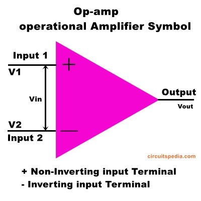
This is the symbol of an opamp. A is the voltage gain, v1 is the non-inverting input and v2 is inverting input.
The differential input is Vin or Vd = V1-V2.
And output voltage Vout = Avin = A(V1-v2). Voltages V1, V2, and Vout are always measured with respect to ground.
An opamp essentially consists of two input terminal and one output terminal. Inputs are marked with the +ve and -ve sign to indicate non-inverting and inverting inputs. Plus (+) sign called non-inverting input and Minus (-) sign called inverting input. If the input signal is applied at the non-inverting terminal, then the output is amplified with the same polarity but if the applied input signal is at the Inverting terminal then the output is amplified but inverted (Reverse) polarity.
Please keep in mind that the plus and minus signs at input never mean for positive voltage supply and negative voltage supply at the input.
The output voltage is directly proportional to input voltage which is the difference of v1 and v2, Vin=V1-V2
Op-amp circuits
1. Inverting amplifier
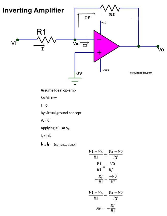
In the inverting amplifier the input voltage is connected with the inverting(-) terminals of op-amp. And another input terminal is grounded. Always used negative feedback with op-amp. The most widely used constant-gain amplifier circuit is the Inverting amplifier. The output is obtained by multiplying the input by a fixed or constant gain.
Op-amp Gain is denoted by Av.
2. Non-inverting amplifier
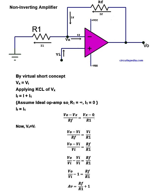
when the input voltage is connected at the Non-inverting(+) terminal then it is called a non-inverting amplifier. In the inverting amplifier the output is amplified and inverted phase of the input signal. But in a non-inverting amplifier, the output is amplified and also the same as the input phase.
Here the input is applied at non inverting(+ve) terminal and the inverting terminal is connected with ground. Always feedback connected with negative.
Differential Amplifier
The output of the differential amplifier is the difference between two voltages. Differential amplifiers amplify the voltage difference between two input lines neither of which is grounded.
as shown in fig the Differential amplifier is the combination of inverting and non-inverting amplifier. When the circuit has two inputs Vin1 and Vin2, the superposition theorem will be used here to determine the gain of the amplifier.
assume Vin1 is 0v, the circuit becomes an inverting amplifier and therefore output voltage due to Vin2 is
Vout2=-Rf/R1Vin2
Now, assumingVin2 =0, Here in this case the circuit is a non-inverting amplifier having a voltage divider network consisting of resistor R2 and R3 at the non-inverting input. Therefore,
This voltage gain Ad of the differential amplifier is the same as the inverting amplifier.
The differential amplifier can be operated in three different modes.
- Single-Ended mode– When the input signal is applied to only one of two input terminals, either of the two input terminals of the two inputs is 0. So in this mode, the differential amplifier will work as either as an inverting amplifier or as a non-inverting amplifier depending on the input signal applied of the inverting or non-inverting terminals.
- Differential mode – In this mode of operation, the magnitude of the two input signals may be the same or different but their Polarity is opposite at every instant of time.
- Common mode – In this mode, the two input signals are the same in magnitude ad also the same in phase at every instant of time. So Input voltage Vin = Vin2 – Vin1 = 0 {because Vin2=Vin1} . So the output voltage is also Zero. Thus there is no output voltage when a differential amplifier is connected in common-mode.
CMRR (Common mode rejection ratio)
The differential amplifier has the features to the ability to reject certain types of noise or undesired voltage signals. these undesired voltage signals or noises are produced by voltage variations in the supply. These undesired signals that appear at both input terminals of the differential amplifier equally will be rejected or canceled out.
CMRR is defined as the ratio of differential voltage gain to common-mode voltage gain and it is given as.
This is a measure of the rejection of signals common to both inputs, and a numerical value assigned, which is called the common-mode rejection ratio.
Higher CMRR ensures that the common-mode signals such as noise are rejected successfully and the output voltage is proportional only to the differential input voltage.
If a differential input change of Y volt produces changes of 1v at the output, and a common mode change of X volts produces a similar change of 1V Then the CMRR is X/Y. when the Common-mode rejection ratio is expressed in DB, it is commonly referred to as common-mode rejection (CMR). CMR is a measure of the rejection of signals common to both inputs, and a numerical value assigned, which is called the common-mode rejection ratio (CMRR).
If a differential amplifier is perfect, CMRR would be infinite because in that case common-mode voltage gain Acm Would be Zero.
Voltage follower or Unity gain of op-amp
or
Unity gain buffer
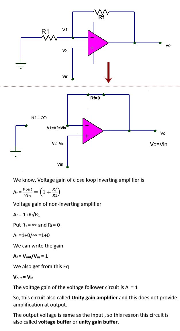
This is a special case of the non-inverting amplifier. When the resistor Rf is set as equal to zero, means this is shorted or resistor R1 is opened or open circuit, so resistor R1 becomes ∞. The Output voltage exactly follows the input voltage both in sign and magnitude. So, this circuit is called the voltage follower.
In the voltage follower, the output voltage follows the input voltage
As the virtual short circuit concept. let us consider both input terminals are shorted internally. so, the potential difference at both inputs is the same. V1 =V2 =Vin
Output voltage = Vout = Vin
Gain with feedback or closed-loop gain of this circuit is 1, so this is also called Unity gain of op-amp
- An operational amplifier is commonly known as op-amp, is basically a multistage, very gain, direct-coupled, negative feedback amplifier.
- An op-amp has an inverting input(-), a non-inverting input (+). and a single output with the reference of ground (0v).
- The value of output depends on the difference between the two inputs.
- op-amp uses voltage shunt feedback to provide stabilized voltage gain.
- the op-amp is called an ideal op-amp then it has 1. infinite open-loop gain. 2 Zero output impedance. 3. Infinite CMRR
- open-loop means that there is no connection between input and output terminal either direct or via another network.
- There are two basic circuits are known as a non-inverting amplifier and an inverting amplifier.
- The differential amplifier is a combination of inverting and non-inverting amplifiers and amplifies the voltage difference between two input lines neither of which is grounded. The differential operation involves the use of opposite polarity inputs.
- The common-mode operation involves the use of the same polarity inputs.
Slew rate (SR)
Slew rate definition
slew rate of an op-amp is defined as the maximum rate at which the output voltage can change. In other word, we can say how fast op-amp is able to respond.
This is a voltage follower, in a voltage follower output signal is the same according to the input signal but in the practical test, the output signal is not the same as the input. This change of the signal is due to the internal compensation of the capacitor. Output signal occurred a delay of some microseconds as the input signal because of capacitor charge time and discharge time of internal ckt. And this result will produce a delay and output is not sharp.
SR=|dv/dt|max
Current flow through the capacitor is Ic=Cdv/dt, dv/dt is the voltage across the capacitor ,dv/dt=Ic/C. This is the rate of change of voltage with respect to time.
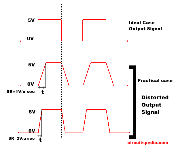
We take an example of a voltage follower circuit. As per the ideal case response at the output signal of the voltage follower is the same as the input signal, which means the waveform of input voltage signal and waveform of the output voltage signal are just the same. But in practical this will not possible and some delay at the output signal we found.
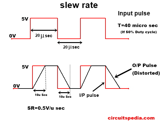
The time taken to reach from 0V to 5V (here denoted by t) depends on the Slew rate of the opamp. If the slew rate of the op-amp is small then the time t is very high and the response rate will very slow. If the slew rate of the op-amp is very high then the response rate of the opamp is very fast. this time t is taken by the charging and discharging the capacitor at the intermediate stage.
The unit of slew rate is v/μsec.
If the slew rate (SR)=1v/μsec, then the time taken (t) by the signal from 0v to 5v is 5μs. If SR= 5v/μs then the signal will reach 0v to 5v within only 1μs, and then the response is fast.
By the slew rate distortion will produce at the output signal of an op-amp.
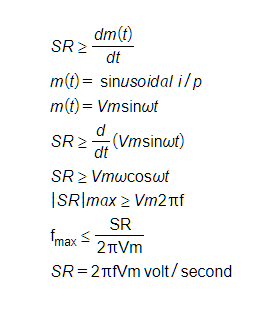
Slew rate Formula
To have minimum distortion (in the sinusoidal waveform)
If f>fmax (Distortion)
If f<= fmax (no distortion)
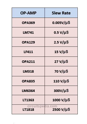
If the slew rate of an op-amp is higher, then the output response is fast and distortion will less. but if slew rate is less of an op-amp, the Output response will slow and distortion will high.
The most commonly used op-amp ICs are LM741, LM358 (dual op-amp), LM324 (quad op-amp) etc.
Also read
-
Thevenin theorem
-
Norton theorem
-
kirchhoff’s law
-
LOGIC GATES
-
How capacitor block dc current
-
What is Impedance (Impedance vs Resistance)
-
Homemade Mini FM Radio Station Transmitter Circuit
